
Servo loop improves linear-regulator efficiency
Linear regulators are widely used in electronic circuits for their simplicity and effectiveness in providing a stable output voltage. Unlike switching regulators, which can introduce high-frequency noise, linear regulators maintain low output noise and provide better transient response. However, the primary drawback of linear regulators is their inefficiency, particularly when there is a significant difference between the input and output voltages. The excess voltage is dissipated as heat, which can lead to thermal management issues in the circuit design.
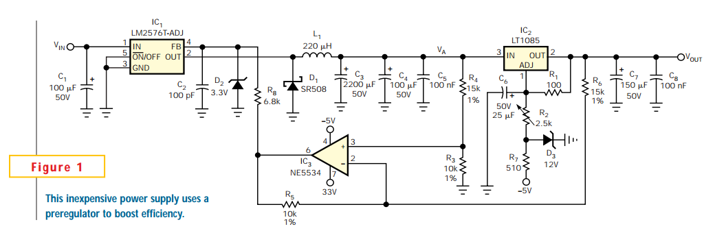
To address the inefficiency problem, several techniques can be employed. One effective method is to utilize a preregulator that reduces the input voltage to the linear regulator. This preregulator can be designed using a switching topology that operates more efficiently than linear regulation. A closed-loop, self-oscillating preregulator incorporates a switching transistor, a comparator, and a filter to regulate the voltage. The switching transistor operates in a pulse-width modulation (PWM) mode, controlled by the comparator, which adjusts the duty cycle based on the output voltage feedback.
The design of such a preregulator involves careful consideration of the frequency response, as the oscillation frequency can impact the stability and performance of the overall power supply. The filter is employed to smooth the output voltage and reduce ripple, ensuring that the linear regulator receives a clean input. While designing this circuit, it is crucial to select components that can handle the expected load current and voltage levels, as well as to account for the thermal characteristics to prevent overheating.
In summary, while linear regulators offer simplicity and low noise, their inefficiency necessitates the use of preregulators to minimize voltage drop and heat dissipation. The implementation of a closed-loop, self-oscillating preregulator can significantly enhance the performance of linear regulators in various applications, making them more suitable for modern electronic designs.Linear regulators are easy to implement and have better noise and drift characteristics than switching approaches. Their largest disadvantage is inefficiency: excess energy dissipated as heat. Several well-known techniques are available to minimize the input-to-output voltage across a linear regulator.
I had been looking for an inexpensive, easy-to-implement, and efficient preregulator to reduce the dropout voltage of a linear regulator. Closed-loop, self-oscillating preregulators built around a switching transistor, a comparator, and a filter are difficult to predict in terms of frequency.
🔗 External reference
Related Circuits
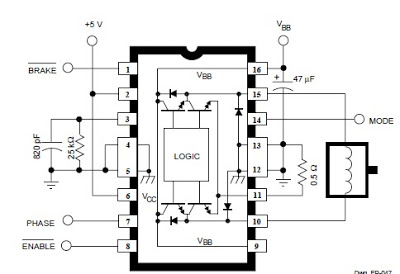
The A3952S integrated circuit, designed by Allegro MicroSystems, can be utilized to create straightforward and effective motor driver circuits. A previous article discussed a basic bipolar stepper motor driver circuit that employs two A3952S circuits. The A3952S is capable...
This is a simple NiCd battery charger powered by solar cells. A solar cell panel or an array of solar cells can charge a battery at more than 80% efficiency, provided the available voltage exceeds the fully charged battery...
A simple, low component count phase locked loop that locks onto and detects the amplitude of an incoming baseband 7 bit Barker code using a switched resistor demodulator that is driven directly by a microcontroller's output pins. Balanced modulators...
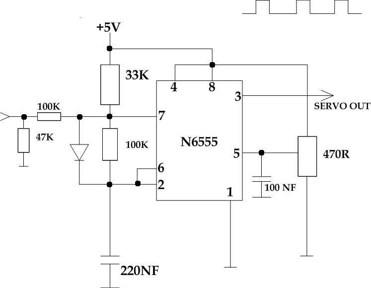
This circuit takes a standard 0-10V control voltage (for example, from an analog light control desk) and outputs a standard 1-2 ms control pulse for RC servo motors. The components used in this circuit include: - 2 x 100...
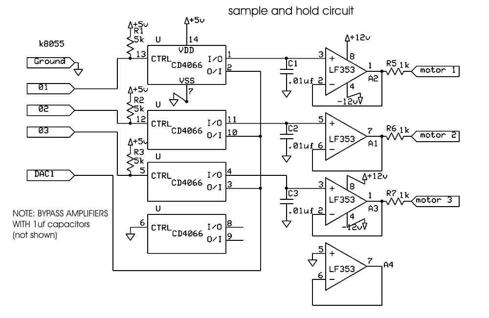
The current Milwaukee Guitar design utilizes an off-board computer (a desktop PC) to control the servomotors. A standard USB number pad is connected to the computer, which provides output signals through a Velleman K8055 USB experiment interface board to...
The current loop interface circuit diagram of the AD694 multi-functional sensor signal conditioner is utilized as a digital-to-analog converter (DAC). This current loop interface enables the conversion of digital values into voltage and subsequently into current signals. The circuit...