
AVR Development Board

The AT90S8535-P microcontroller, housed in a DIP40 package, is a versatile component suitable for various embedded applications. Its pin compatibility with other AVR microcontrollers, such as the ATMega8535 and ATMega16, allows for easy integration into existing designs, albeit with careful consideration of their differing specifications.
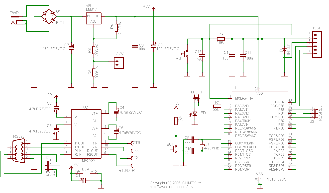
The external clock circuit is crucial for the microcontroller's operation, utilizing an 8 MHz crystal (designated as Q1) paired with capacitors C10 and C11, which should be selected within the range of 12 to 47 pF to ensure stable oscillation. The choice of these capacitors is influenced by the crystal's specifications and the desired frequency stability.
The RESET circuit is designed for reliable operation, comprising a 10 KΩ resistor (R1) and a 10 µF capacitor (C1) rated for 10 V. While these component values are not critical due to the internal signal conditioning capabilities of the AT90S8535, they provide additional robustness against noise and voltage fluctuations during startup.
Digital input lines are interfaced through PORTC, with pull-up resistors connected to Vcc to maintain a HIGH idle state. This configuration allows for reliable detection of input signals, where an active input line is established when the line is pulled to ground, typically achieved through a relay contact. The inclusion of status-indicating LEDs enhances the design by providing visual feedback on the state of each input, facilitating debugging and operational monitoring.
Overall, the AT90S8535-P microcontroller, combined with its supporting circuitry, offers a robust platform for various applications, with careful attention to component selection and circuit design ensuring reliable performance.The microcontroller is an AT90S8535-P in a DIP40 package. Note that this microcontroller is pin by pin, hardware compatible with other members of the analog series of AVR microcontrollers, like ATMega8535 and ATMega16. However, there are many differences between these microcontrollers. Consult the data sheets before making the replacement. The ext ernal clock circuit uses an 8 MHz crystal, Q1, and the capacitors C10, C11 (12 47 pF). The RESET circuit consists of the resistor R1 (10 K), and the capacitor C1 (10 F/10 V). These values are not critical, because AT90S8535 contains internal signal conditioning circuits for the RESET signal. The digital input lines are connected to PORTC, and are pulled up to V cc with resistors. A group of LEDs has been included, to show the status of each input. The idle status of the input lines is HIGH. An input line is active when pulled to GND (for example by the contact of a relay). In this case, the associated LED will light, indicating the. 🔗 External reference
Related Circuits
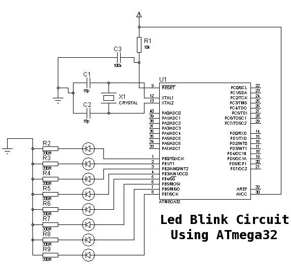
This is a basic tutorial for beginners using the ATmega32 microcontroller to get started. This program can be referred to as a "Hello World" for the ATmega. The ATmega32 microcontroller is a member of the AVR family, widely utilized in...
This document serves as a continuation of the previous work on PWM controllers utilizing 555 timers. The new design incorporates microcontrollers and MOSFETs in place of the 555 integrated circuits and transistors. Two versions have been developed: one equipped...
H-Bridge circuit utilizing transistors for the bidirectional control of a DC motor. Integrated circuits (ICs) containing H-Bridges are employed to simplify the drive circuit. The L293D is a dual H-Bridge motor driver, allowing for the control of two DC...
This project is designed to assist in a basic course where students create a simple AVR/Arduino-based badge. It serves as a beginner's soldering project, resulting in a small object with blinking lights that can be worn around the neck...
The module provides a pre-wired multiplex of a 4-digit common anode LED, which is quite useful. The soldering pad for these signals is shown in the first picture below. A friend provided an AT90S2313 chip, along with a simple...
For applications requiring numerous Analog to Digital channels or substantial program memory (up to 32K), this prototype board is ideal. It is designed for 40-pin PIC microcontrollers and includes a power supply circuit, a 20MHz crystal oscillator circuit, an...