
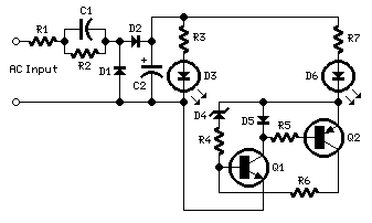
Balance Indicator

The described amplifier circuit utilizes a pair of stereo potentiometers (P1 and P2) to achieve both balance and level control. The configuration allows for a straightforward adjustment of the audio balance between two channels, with the bridge circuit providing a clear representation of the channel balance. The voltage measurement across the wipers of the potentiometers is crucial, as it directly correlates to the balance; thus, a lower voltage indicates a more balanced signal output.
In addition to the basic functionality, the integration of a center-zero moving coil meter enhances the user interface, allowing for a visual indication of the balance status. The bias resistor connected to the meter ensures accurate readings by establishing a reference point in the circuit. The removal of the zener diodes simplifies the design when the LED indicators are not required, streamlining the circuit while maintaining essential functionality.
The differential amplifier configuration using IC1 plays a pivotal role in processing the signals, with resistors R5 and R6 ensuring that the LEDs receive appropriate biasing to indicate the balance status effectively. The virtual ground created by these resistors allows the circuit to operate correctly with an asymmetrical power supply, which is common in many audio applications. The sensitivity of the circuit is particularly noteworthy; the ability to light the LEDs at a mere 40 mV demonstrates the precision of the design, making it suitable for applications where fine-tuning of audio levels is critical.
Overall, this circuit design exemplifies a robust solution for achieving balance control in audio amplifiers, providing both functional and visual feedback to the user while maintaining simplicity and effectiveness in operation. If your amplifier is fitted with two level controls, it actually offers you a balance control and a level control. A draw back of this is that it is quite difficult to set the balance properly. This can be obviated, however, by replacing the two monopotentiometers with stereo versions PI and P2 in the diagram. One half of the pair, P1A and P2A, assumes the tasks of the removed components. The other half Is connected in a bridge circuit. The voltage between wipers of the potentiometers is then a measure of the balance between the two channels.
The lower the potential, the better the balance. If you are interested in knowing the degree of unbalance, connect a center-zero moving coil meter with a bias resistor between A and B. With this arrangement, zener diodes Dl and D2 can be omitted: they are necessary only with the LED indicator shown in the diagram to prevent the input voltage of the op amp from getting too close to the level of the supply voltage.
The circuit around IC1 is a classical differential amplifier. Resistors R5 and R6 provide a virtual earth for the LEDs, which is necessary to ensure that, in spite of the asymmetrical supply voltage, a positive and a negative output is obtained. Because the LEDs have been included in the feedback loop of the indicator, the circuit is pretty sensitive.
At only 40 mV, that is, just 1Uoo of the supply voltage, one of the LEDs begins to light. The maximum current drawn by the LEDs is determined by the values of R5 and R6. 🔗 External reference
Related Circuits
This circuit, designed on request, has proven to be useful to indicate when the voltage in a power supply line is changing from 120V to 240Vac. It can be used in different circumstances and circuits, mainly when an increase...
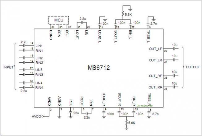
The MS6714 is a digital control audio processor designed for low voltage operation, featuring four stereo inputs and two-channel outputs. It integrates volume control, tone adjustments (bass and treble), and balance control (left/right) within a single chip. The MS6714...
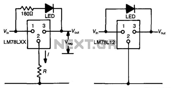
The three-terminal regulator device (LM78LXX) provides an output voltage (Vout) equal to the input voltage (Vm) until the input voltage exceeds the output voltage by 1.5 to 2 volts. A regulated voltage (Vreg) is achieved at this point, with...
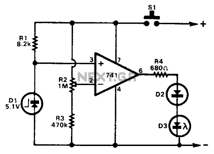
The 741 operational amplifier can function as a voltage comparator. It features a non-inverting input and a Zener-controlled voltage source, with a reference voltage set at 5.1V. Resistor R2 is used to adjust the in-phase input voltage to half...
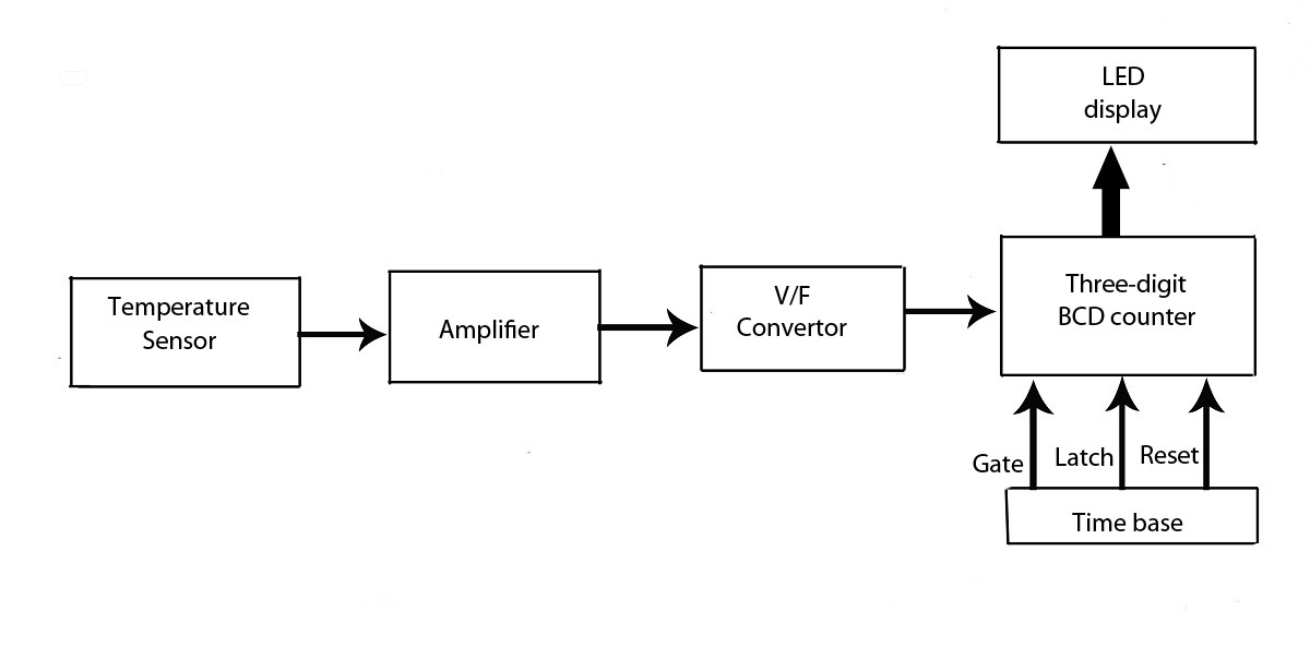
This verified project provides an idea, circuit, and operation of the LED display temperature indicator. It features a digital temperature indicator utilizing a voltage-to-frequency (V/F) converter, along with various electronic projects. The LED display temperature indicator is designed to provide a...

When the lamp turns off, a reset pulse is generated for the corresponding counter by NAND gate IC1. The counter then counts up again. The display's progression rate can be adjusted to the desired speed using potentiometer P1. Only...