
BALANCED MODULATOR FOR ADF

The circuit described is integral to the operation of an automatic direction finder (ADF), which is essential in navigation systems. The primary function is to combine the signals received from loop and sense antennas, allowing for accurate directional information to be extracted.
The loop antenna is designed to pick up signals from a specific direction, while the sense antenna captures signals from all directions. The combination of these signals is crucial for determining the angle of arrival of a radio frequency signal. The output frequency of 130 cycles per second (cps) is significant, as it is tuned to the operational requirements of the resolver, which is a type of rotary electrical transformer used for measuring angular position.
The circuit employs phase manipulation techniques to ensure that the output signal is correctly phased. This is essential for the rotor of the resolver to be driven to the null position, indicating that the ADF is accurately aligned with the incoming signal. By achieving this null position, the system can provide precise directional information, which is vital for navigation and positioning applications.
The implementation of servo filters and gain control within the circuit enhances the performance of the ADF. Servo filters help in stabilizing the output signal by filtering out noise and unwanted frequencies, while gain control adjusts the amplitude of the output signal to ensure optimal performance under varying signal conditions.
Overall, this circuit plays a critical role in the functionality of automatic direction finders, contributing to the accuracy and reliability of navigation systems in various applications, including aviation, maritime, and land-based navigation.Combines signals from loop and sense antennas of automatic direction finder, to give 130-cps output having correct phase for driving rotor of resolver to null position.-P. V.Sparks, Servo Filter and Gain Control lmprove Automatic Direction Finder, Electronics, 34:23, p 110-113..
🔗 External reference
Related Circuits
In the 555 datasheet, there is a pulse width modulation circuit that resembles this one, with the only difference being that pin 5 is labeled as 'audio'. The 555 timer IC is a versatile device commonly used in various applications,...
The design consists of differential compound pairs of transistors with a common mode (floating) gain control connecting the emitters of the pair. The compound pairs of 2N4403 and BC549s are far more linear than any single transistor. The circuit...
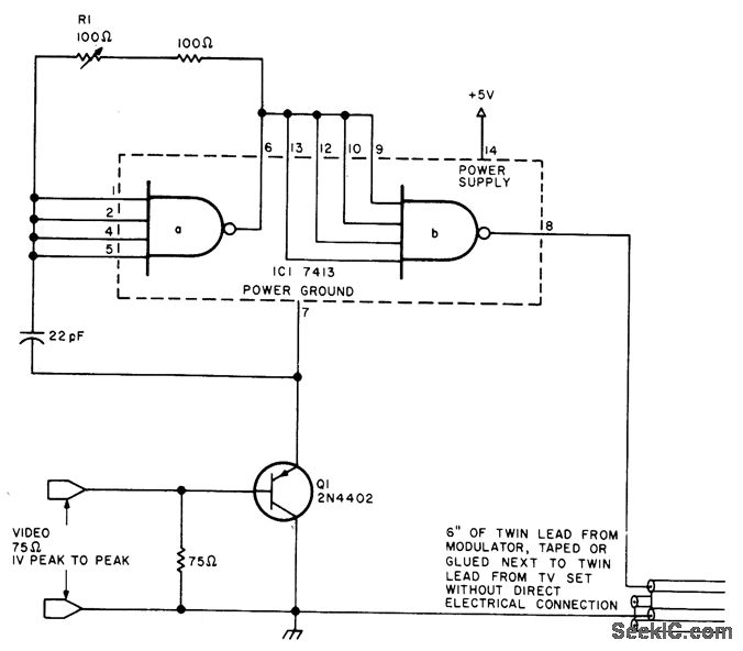
The first section of a free-running 7413 Schmitt-trigger oscillator operates at one-third of the desired TV channel carrier frequency, approximately 20 MHz for channel 3. This oscillator drives a buffer section that produces a square wave at the oscillator's...

This circuit includes an amplifier designed to deliver +10 dBm to an SBL series (Mini-Circuits) or a similar type of doubly-balanced mixer assembly. The circuit parameters are specified for 80 to 90 MHz crystals, although the values of the...
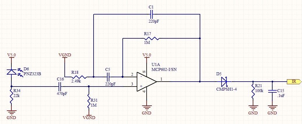
Designing an infrared (IR) demodulator circuit to replace the one shown in this question. The goal is to demodulate a simple IR signal modulated at 32.678 kHz, with the requirement of detecting the presence of the signal without packet...
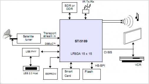
The STI5211 is a standard definition, full back-end processor designed for satellite set-top boxes, adhering to ATSC, SMPTE VC-1, DVB-S2, DIRECTV, DCII, and ARIB BS4 specifications. It delivers high performance for low-cost standard definition systems. Compared to the STi5202,...