
Bedini/Cole Bipolar switch
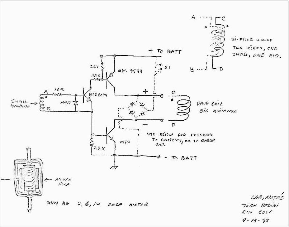
The described circuit features a configuration designed to harness electromagnetic induction. The two trigger coils serve as sensors that detect the movement of the north pole magnets affixed to the rotating wheel. As the magnets pass by the trigger coils, they induce a voltage in the coils due to the changing magnetic field, which can be used to generate electrical pulses.
The two power coils are likely intended to convert the induced voltage into usable electrical energy. This energy can be used to power a load or recharge a battery. The design may incorporate a rectifier circuit to convert the alternating current (AC) generated in the coils into direct current (DC), suitable for powering electronic devices.
The reed switch acts as a control mechanism in this setup. It is a type of electromechanical switch that closes when exposed to a magnetic field. In this circuit, the reed switch could be used to activate or deactivate the power coils based on the presence of the magnetic field from the north pole magnets. This feature allows for precise control over the timing of energy generation, ensuring that the power coils are only active when necessary.
The wheel's configuration, with four north pole magnets, ensures that as it rotates, the trigger coils experience multiple magnetic field changes, leading to the generation of nine radiant pulses per complete rotation. This design maximizes the efficiency of energy harvesting from the mechanical rotation, making it suitable for applications such as renewable energy generation, where mechanical motion is converted into electrical energy.
Overall, this schematic represents an innovative approach to energy generation through electromagnetic induction, with a focus on optimizing the interaction between magnetic fields and coils to produce a reliable electrical output.My modification, i have two trigger coils , two power coils, one reed switch. The wheel is 4 north pole magnet, it generates 9 radiant pulses per.. 🔗 External reference
Related Circuits
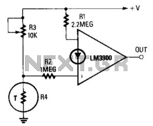
The reference current is supplied from the supply voltage through resistor R1 to the inverting terminal, while the variable (non-inverting) current is sourced from the junction of resistors R3 and R4. Since the value of R1 is approximately double...
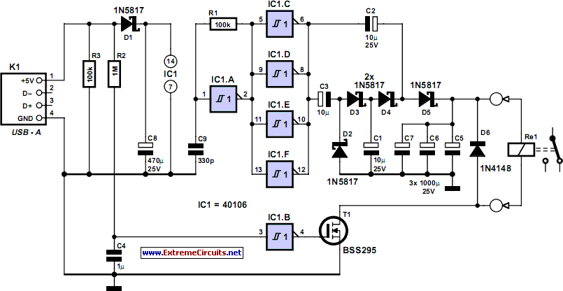
The circuit automatically powers down a computer after Windows has been shut down, preventing users from forgetting to turn off their machines. Upon shutting down Windows, a click occurs after one second, disconnecting the PC from the mains supply....
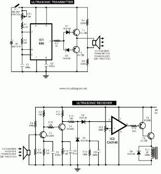
This is an ultrasonic motion detector circuit with high movement sensitivity. It can detect even minor air movements, such as hot air rising or wind blowing, when the trimpot is adjusted to a sensitive position. The transmitter emits a...
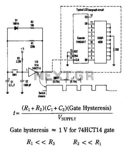
This circuit generates an output pulse when the pushbutton SW1 is pressed. It also functions as a hysteresis gate oscillator. Diode D1 and resistor R2 introduce asymmetry into the circuit. The delay before repeat time (DBRT) is influenced by...
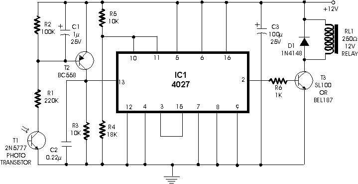
Using dual flip-flop IC CD4027 employ a 555 based monostable circuit to supply input clock pulses. The circuit described here obviates this requirement. One of the two flip-flops within IC CD4027 itself acts as square wave shaper. The circuit utilizes...
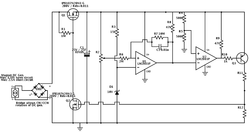
A flywheel-driven permanent magnet DC generator is used to charge a bank of supercapacitors rated at 35 farads and 25V. The maximum charge voltage is limited to 22V using a comparator and a zener reference due to the absence...