
Cmos Based Vehicle Anti-Theft Alarm
The circuit design incorporates several critical features aimed at enhancing vehicle security through automatic alarm activation and immobilization. The automatic exit and entry delays ensure that the user has adequate time to exit and re-enter the vehicle without triggering the alarm unintentionally. The optional instant alarm feature allows for additional protection in vulnerable areas of the vehicle, such as the hood and trunk, providing flexibility in security options.
The use of a CMOS 4011 logic gate facilitates the control of the siren output, allowing for customization between intermittent and constant sound patterns based on user preference. The design also includes provisions for additional switches, which can be strategically placed to cover potential entry points, further fortifying the vehicle against unauthorized access.
The timing components, R1, C1, R9, C4, R7, and C3, are crucial in defining the operational parameters of the alarm system. Their selection should be made with attention to the tolerances and characteristics of the components to ensure reliable performance. While the precise timing may vary, the system is designed to function adequately without requiring extreme accuracy.
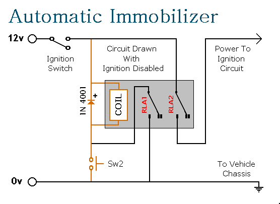
The integration of a relay for immobilization is a significant feature, as it prevents unauthorized starting of the vehicle once the ignition is turned off. The design ensures that the relay operates without drawing current when the ignition is off, thus preserving battery life. The requirement for a momentary push switch to re-enable the system adds a layer of security, as it necessitates user interaction to restore functionality.
Overall, the circuit's design emphasizes both security and user convenience, with features that minimize the risk of false alarms while maximizing protection against theft. The careful selection of components and the inclusion of safety measures, such as the in-line fuse, underscore the importance of reliable operation in automotive applications.This circuit features automatic exit and entry delays - an optional instant alarm zone - an optional intermittent siren output - and an automatic reset. By adding external relays you can immobilize the vehicle and flash the lights. The alarm is set by opening Sw1. It can be any small 1-amp single-pole change-over switch - or for added security you could use a key-switch. For automatic operation - use the contacts of a small relay in place of Sw1. Wire the relay coil so that it`s energized while the ignition is on. Then - every time you turn the ignition off - the alarm will set itself. Once Sw1 is opened you have about 10 to 15 seconds to get out of the vehicle and close the door behind you. When you return and open the door the buzzer will sound. You have 10 to 15 seconds to move Sw1 to the off position. If you fail to do so - the siren will sound. The output to the siren is intermittent. That is - it switches on and off. The speed at which it switches on and off is set by C6 & R10. If you want a constant siren output - leave out C6 & R10 - and connect pins 8 & 9 of the Cmos 4011 together.
One of the alarm`s inputs is connected to the vehicle`s existing door-switches. This provides the necessary exit and entry delays. It`s usually sufficient to connect a single wire to just one of the door switches. These switches are generally all connected in parallel - with the return through the chassis. You can add extra normally-open switches to the door-circuit if you wish - but note that any additional switches will have to be able to carry the current required by your vehicle`s interior light. Any number of normally-open switches may be connected - in parallel - to the "Instant" input. Since they don`t have to carry the current for the interior light - you can use any type of switch you like.
You may want an instant alarm on the bonnet - the boot - the rear-hatch - the rear-doors etc. It doesn`t matter if these already have switches connected to the door-circuit. Simply fit a second switch and connect it to the instant input. It will override the delay circuit. You can use the chassis for the return. However, a ground terminal is provided if - for any reason - you need to run a separate return wire for either zone. If you`re not using the instant zone then leave out D3 and the four components coloured grey in the diagram - that is Q2, R3, R4 & R5.
The exit delay is set by R1 & C1 - the entry delay by R9 & C4 - and the reset time by R7 & C3. The precise length of any time period depends on the characteristics of the actual components used - especially the tolerance of the capacitors and the exact switching points of the Cmos gates. However - for this type of application - really accurate time periods are unnecessary. While any trigger-switch remains closed - the siren will continue to sound. About 2 to 3 minutes after all of the switches have been opened - the alarm will reset. The circuit is designed to use an electronic Siren drawing 300 to 400mA. It`s not usually a good idea to use the vehicle`s own Horn - because it can be easily located and disconnected.
However - if you choose to use the Horn - remember that the alarm relay is too small to carry the necessary current. Connect the coil of a suitably rated relay to the "Siren" output. This can then be used to sound the Horn - flash the lights etc. The Support Material for this circuit includes a step-by-step guide to the construction of the circuit board, a parts list, a detailed circuit description and more.
The circuit board and switches must be protected from the elements. Dampness or condensation will cause malfunction. Fit a 1-amp in-line fuse AS CLOSE AS POSSIBLE to your power source. This is VERY IMPORTANT. The fuse is there to protect the wiring - not the alarm. Exactly how the system is fitted will depend on the make of your particular vehicle. Consequently, I CANNOT give any further advice on installation. Before fitting this or any other immobilizer to your vehicle - carefully consider both the safety implications of its possible failure - and the legal consequences of installing a device that could cause an accident. If you decide to proceed - you`ll need to use the highest standard of materials and workmanship. Remember that the relay MUST be large enough to handle the current required by your ignition system. Choose one specifically designed for automobiles - it will be protected against the elements and will give the best long-term reliability.
You don`t want it to let you down on a cold wet night - or worse still - in fast moving traffic! Please note that I am UNABLE to help any further with either the choice of a suitable relay - or with advice on its installation. When you turn-off the ignition, the relay will de-energize and the second set of contacts (RLA2) will break the ignition circuit - automatically immobilizing the vehicle.
When the ignition is switched on again the relay will not energize - and the vehicle`s ignition circuit will remain broken. You must press Sw2 to energize the relay. It then latches itself on using the first set of contacts (RLA1) - while the second set of contacts (RLA2) completes the connection to the ignition circuit.
The design has a number of advantages. It operates automatically when you turn off the ignition - so there`s no need to remember to activate it. The relay uses no current while the ignition is off - so there`s no drain on the battery. To de-activate it you`ll need to have the ignition key and you`ll need to know the whereabouts of the push-switch.
Sw2 only requires a single wire because its return is through the chassis. It carries no load other than the current required by the relay-coil. So almost any small "momentary-action, push-to-make" switch will do. For extra security Sw2 could be key-operated. 🔗 External reference
Related Circuits
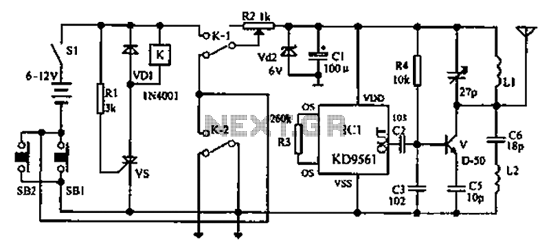
As environmental awareness increases, electric cars have become an essential part of people's transportation. Preventing electric car theft is a significant concern for owners. Various electric vehicle anti-theft locks have been developed; however, theft of electric cars continues to...

In the event of a sudden power failure in an elevator, it is crucial for the duty officer in the distribution room to be alerted promptly to prevent panic among passengers trapped inside. The following describes a sound alarm...
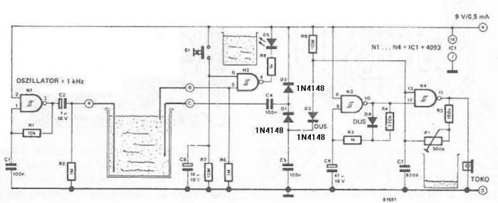
The circuit diagram is straightforward and operates as follows: the N1 Schmitt trigger functions as an oscillator, producing a frequency of approximately 1 kHz. When there is sufficient water in the tank, alternating voltage flows from electrode A to...

This alarm siren circuit produces a continuous frequency sweep, resulting in a warbling sound. The duration of the warbling is approximately 6 seconds, with 3 seconds allocated for frequency sweeping upward and 3 seconds for sweeping downward. The alarm siren...
The original smoke alarm circuit has several issues that have disappointed hobbyists and students. Instead of attempting to fix these problems, an update has been created using the well-known LM741 operational amplifier. This new design is simpler, more conventional,...
This circuit utilizes LM358 operational amplifiers (or any single supply operational amplifier) to generate a pulse-width modulated (PWM) signal. The design was specifically created for a local marine repair company that requested a circuit that is easily repairable and...
Warning: include(partials/cookie-banner.php): Failed to open stream: Permission denied in /var/www/html/nextgr/view-circuit.php on line 713
Warning: include(): Failed opening 'partials/cookie-banner.php' for inclusion (include_path='.:/usr/share/php') in /var/www/html/nextgr/view-circuit.php on line 713