
Count Down Timer Relay with 555

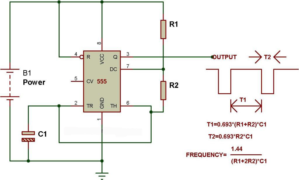
The circuit described utilizes a 555 timer IC configured in an astable mode to generate a square wave output, which serves as the clock signal for a 14-stage binary ripple counter, specifically the 4020 or 14020 model. The operation of the 555 timer in astable mode allows it to oscillate continuously, producing a square wave with a frequency determined by the resistor and capacitor values connected to it. The inclusion of a potentiometer enables fine-tuning of the frequency to achieve a precise output period of 1 second, which is essential for applications requiring accurate timing, such as LED flashing.
The output from the 555 timer (pin 3) is directly connected to pin 10 of the ripple counter, facilitating the counting operation. The 4020 ripple counter is capable of counting up to 8192 pulses, with various output options available through a jumper configuration. This flexibility allows the user to select a specific count output, which can be useful for timing applications across a wide range of intervals.
The circuit incorporates a power-on reset feature, utilizing capacitor C3, resistor R4, and diode D1. When power is initially applied, C3 is discharged, pulling pin 11 high and ensuring that the counter starts in a known state (all outputs low). As C3 charges through R4, pin 11 transitions low, enabling the counter to begin counting the clock pulses generated by the 555 timer. This design ensures reliable operation and prevents erroneous counts due to power fluctuations.
The ripple counter's counting mechanism advances the count on the negative edge of the clock pulse, effectively doubling the count for each complete cycle of the 555 output. This characteristic allows for precise control over the timing intervals, making the circuit suitable for applications requiring extended timing durations, such as timers or event counters. The overall design exemplifies a practical application of fundamental electronic components, showcasing the integration of timing and counting functionalities in a cohesive circuit.The 555 is configured in the standard astable oscillator circuit designed to give a square wave cycle at a period of around 1 cycle/sec. A potentiometer is included in the design so the period can be set to exactly 1 second by timing the LED flashesc.
A jumper connection is provided so the LED can be turned off. As soon as power is applied to the circuit counting begins. We have not reviewed the operation of the 555 IC here. Most electronic magazines review it in detail once every few years. And it is a standard feature in most intoductory electronic text books. The output pulse from pin 3 of the 555 is fed to a the clock input pin 10 of the 14-stage binary ripple counter, the 4020 (or sometimes 14020.) You can see from the schematic that the LED input is taken directly from this connection. Ripple Counter: The counter output wanted is set by a jumper. Eleven counter outputs are available: 8 counts, 16 32 64 128 256 512 1024 4096 and 8192 counts. If the 555 is set to oscillate at exactly 1.0Hz by the on-board trimpot then the maximum timer interval which can be set is 8192 seconds (just over 2 hours.) At the end of the counting period a pulse is output on the pin with the jumper on it.
The 14020 ripple counter advances its count on each negative transistion of the clock pulse from the 555. So for each output cycle of low-high-low-high the count is advanced by two. It can be set to an zero state (all outputs low) by a logic high applied to pin 11. In this circuit C3, R4 and D1 are arranged as a power-on reset. When power is applied to the circuit C3 is in a discharged state so pin 11 will be pulled high. C3 will quickly charge via R4 and the level at pin 11 falls thus enabling the counter. The 14020 then counts clock pulses until the selected counter output goes high. D1 provides a discharge path for C3 when the power is disconnected. 🔗 External reference
Related Circuits
This circuit turns off an amplifier or any other device when a low-level audio signal fed to its input is absent for 15 minutes at least. Pushing P1, the device is switched on, feeding any appliance connected to SK1....
The schematic presented originates from buildcircuit.com. This circuit functions as a music generator, infrared transmitter, and LED blinker, depending on the values of R1, R2, and C1. A minor modification to the previous circuit allows it to operate as...
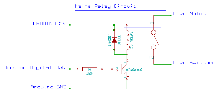
This mains AC relay module utilizes 5V relays that can be powered directly from an Arduino and can switch 230V. A basic energy monitoring and control system has been constructed using an Arduino 2009, off-the-shelf wireless remote control sockets,...
This circuit is designed for the selection of alternative sources. It integrates mechanical selection through a rotating switch S1, electronic control of relays RL1 to RL10, and optical indication of the selection via the display DSP1. The circuit operates by...
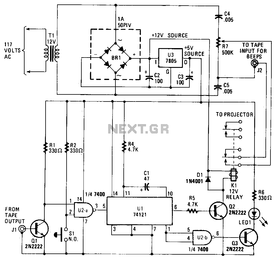
This circuit records commentary and music on one track of a tape while placing beeps that signal slide changes on another track. The gate U2a triggers U1, which is configured as a timer that generates a pulse each time...
This is a simple circuit designed for an audio amplifier project to control the speaker output relay. The purpose of this circuit is to manage the delay that activates the relay, which connects the speakers to the audio amplifier....