
General Infrared Remote Controlled Relay

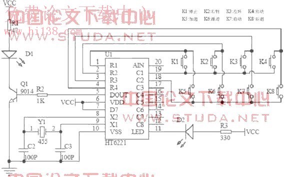
The relay circuit described functions by receiving signals from an infrared (IR) remote control, which typically operates at a frequency of around 38 kHz. The circuit is designed to decode these IR signals and activate a relay, allowing for the control of various electronic devices.
The core components of the circuit include an infrared receiver module, a microcontroller or a dedicated decoder IC, and a relay. The infrared receiver module detects the IR signals emitted by the remote control. Upon receiving a signal, the module outputs a digital signal to the microcontroller or decoder IC.
The microcontroller processes the received signal and determines the corresponding action based on the specific button pressed on the remote control. This processing may involve simple logic or more complex programming, depending on the desired functionality. The output from the microcontroller is then used to energize the relay coil, which closes or opens the relay contacts, thereby controlling the connected load.
Power supply considerations are crucial for the proper operation of the circuit. The circuit typically requires a regulated power source that can supply the necessary voltage and current for both the infrared receiver and the relay. Commonly used relays can handle various loads, allowing the circuit to control appliances such as lights, fans, or other electronic devices.
In summary, this relay circuit provides a versatile solution for remote control applications, leveraging the widespread use of infrared remote controls to enable wireless operation of electrical devices.This relay circuit is controlled by almost any type of infrared remote controller. This circuit works on assumption that almost all remote controller use high.. 🔗 External reference
Related Circuits
An infrared remote control car utilizes the AT89S51 microcontroller as the core controller. The system operates DC motors via L298 drivers, enabling manual control, autopilot, and tracking functions. The software is modular and developed using the C programming language....
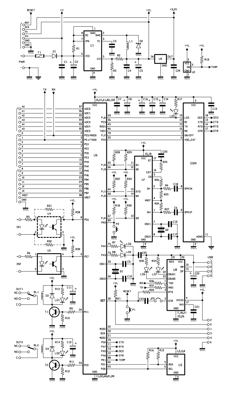
Utilizing the ATmega 2560, which serves as the core of the Arduino platform, a universal remote control with GSM capabilities has been developed. This device allows for the control of 2 inputs and 2 outputs, DTMF key functionality, gate...
This is a power-on time delay relay circuit that utilizes the emitter/base breakdown voltage of a standard bipolar transistor. The reverse-connected emitter/base junction of a 2N3904 transistor functions as an 8-volt zener diode, establishing a higher turn-on voltage for...
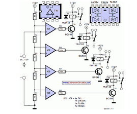
This circuit demonstrates that microprocessors, personal computers, and the latest ultra-accurate digital-to-analog converters (DACs) are excessive for the task of sequentially controlling four relays. The circuit utilizes a simple microcontroller or a basic timer IC to manage the operation of...
The YouTube video below demonstrates the quick and easy setup of the system at the launch site. The provided description indicates a focus on the efficiency of system installation at a launch site, as showcased in a YouTube video. In...
This relay circuit is controlled by nearly any type of infrared remote controller. It operates under the assumption that most remote controllers utilize high-frequency modulated infrared light. By filtering out unmodulated or low-frequency modulated signals, this circuit effectively eliminates...
Warning: include(partials/cookie-banner.php): Failed to open stream: Permission denied in /var/www/html/nextgr/view-circuit.php on line 713
Warning: include(): Failed opening 'partials/cookie-banner.php' for inclusion (include_path='.:/usr/share/php') in /var/www/html/nextgr/view-circuit.php on line 713