
Random number with led 1 digit

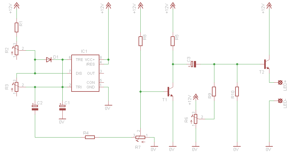
The described circuit utilizes the LM555 timer IC, which operates in a multistable mode to generate a sequence of outputs that can drive a 7-segment LED display. In this configuration, the LM555 is set up with two resistors (R1 and R2) and a capacitor (C2) to create a timing circuit that allows the LED segments to light up in a random pattern.
The multistable mode of the LM555 timer enables the circuit to toggle between various states based on the input conditions. The resistors R1 and R2 determine the charge and discharge times of capacitor C2, thereby influencing the timing intervals between the changes in the LED display. This results in a visually dynamic effect as different segments of the display illuminate in a seemingly random sequence.
For implementation, the circuit connections must be made carefully to ensure that the LM555 is powered correctly, typically with a voltage supply between 4.5V and 15V. The output pins of the LM555 can be connected to the anodes of the 7-segment display, while the common cathode is connected to ground. The configuration of the resistors and capacitor should be chosen based on the desired speed of the LED transitions.
In summary, this circuit diagram effectively demonstrates the random lighting behavior of a 7-segment LED display using an LM555 timer in a multistable configuration, with the timing components (R1, R2, and C2) playing a crucial role in determining the display's dynamic characteristics.This is a circuit diagram showing the random nature of LED 7 segment. In the diagram circuit IC1 - LM555, R1, R2 and C2 on the circuit a sensitive multi-Stable. 🔗 External reference
Related Circuits
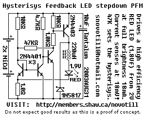
Below is a proof of concept circuit which needs improvement. The part values shown will run a high efficiency red LED with a Vf of 1.9V from only 2 nicads, right down to 2 volts. For a white LED...
An AC mains operated single LED flasher circuit is designed using the widely used CMOS timer chip TLC555. The entire circuit is powered directly by the grid supply of 230VAC through a capacitive potential divider and associated components. This LED...
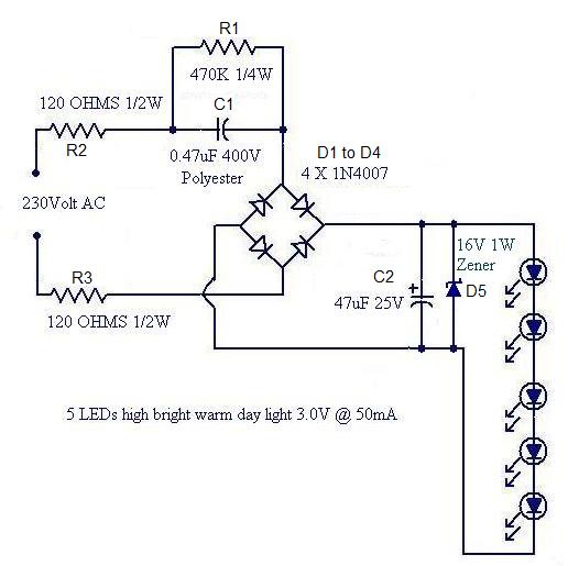
Convert a used CFL into a power-saving LED lamp circuit that consumes only 50mA. This gadget can be used in applications like a night light, table lamp, etc. The project involves redesigning a compact fluorescent lamp (CFL) to function as...
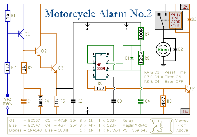
This circuit features an intermittent siren output and automatic reset. It can be operated manually using a key switch or a hidden switch; however, it can also be wired to activate automatically when the ignition is turned off. By...
This emergency LED light is simple, inexpensive, and easy to build. The circuit connects to the battery, activating when the main power source is unavailable, such as during brownouts. White LEDs turn on automatically. Initially, the output voltage from...
This circuit simulates a breathing or pulsing LED using a 555 timer chip. It has gained popularity, receiving numerous comments and emails from users who successfully built the circuit, as well as feedback from those who encountered difficulties when...