
Bidirectional H-Bridge DC-Motor Motion Controller

The integration of armature resistance cancellation in DC servo motors is a significant advancement in enhancing performance and efficiency. This technique utilizes positive current feedback to compensate for the voltage drop across the armature resistance, which typically reduces the effective voltage supplied to the motor. By effectively canceling this resistance, the system can maintain higher torque and improve response times during operation.
In conjunction with this technique, the motion-reversing H-bridge circuit topology plays a critical role in the control of the motor's direction and speed. An H-bridge configuration enables the reversal of current flow through the motor, allowing for bi-directional control. The H-bridge consists of four switches (transistors or MOSFETs), arranged in a bridge configuration. By selectively turning on pairs of switches, the voltage across the motor can be controlled to either drive it forward or reverse.
The combination of these two elements allows for precise speed control of the DC servo motor. The positive current feedback ensures that the motor operates efficiently across various load conditions, while the H-bridge provides the flexibility to change direction instantly. This sophisticated control mechanism is particularly beneficial in applications requiring rapid changes in motion, such as robotics, CNC machinery, and automated systems.
In summary, the synergy between armature resistance cancellation and the H-bridge circuit topology results in a robust, efficient, and versatile DC servo motor control system, capable of delivering high performance in demanding applications.Combining armature resistance cancellation (via positive current feedback) with a motion-reversing H-bridge circuit topology offers a new twist in dc servo motor speed control 🔗 External reference
Related Circuits
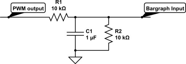
For a project, there is a need to display a progress bar representing the activity performed by a microcontroller unit (MCU). A bar graph display is intended for this purpose; however, the bar graph display driver IC, LM3914, requires...
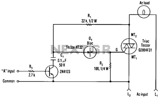
The single transistor connected between the capacitor and the common side of the AC line allows a logic-level signal to control this TRIAC power circuit. Resistor R2 prevents false triggering of the TRIAC by the trickle current through the...
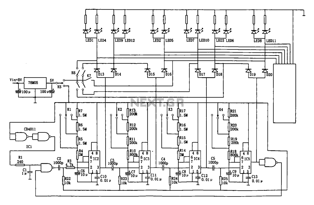
This document describes an automatic traffic intersection light control circuit. It features four monostable delay circuits, which consist of four 555 timer integrated circuits (IC2 to IC5) and several RC components interconnected. An 8V input voltage is regulated through...
This design is intended as a dimmer for a 12V reading lamp, but it can also function as a motor speed controller for devices like drills. The circuit modulates the voltage supplied to the load, allowing for variable pulse...
To achieve greater sensitivity, consider using the 74AC04 or 74HC04 in place of the 74HCU04 for component U1. While the 74AC04 and 74HC04 may offer improved performance over the 74HCU04, it is important to note that the frequency response...
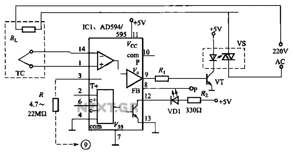
An automatic electric furnace temperature controller is depicted in FIG. 1-25. The closed circuit is established through a temperature detection output control loop. As the temperature rises, the output voltage increases. When the voltage reaches a preset temperature value,...