
Binary counter

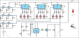
The described circuit utilizes a silicon-controlled switch (SCS) for controlled switching applications. The SCS operates by being triggered on when a positive voltage is applied to the cathode gate, allowing current to flow from the anode to the cathode. The SCS remains in the on state until a negative voltage is applied to the anode gate, effectively turning it off. This method of control is particularly useful in applications requiring precise timing and switching capabilities.
In conjunction with the SCS, a diode (IN4009) is employed to protect the circuit from positive voltage transients that may occur during operation. The diode is oriented to conduct in the reverse direction, thereby clamping any excessive voltage spikes that could potentially damage the SCS or other components in the circuit. This transient suppression is crucial during the recovery phase of the SCS, where it may be vulnerable to high voltage levels.
The input stage of the circuit is designed to generate fast positive edges, which are essential for triggering a counter. This rapid transition can be achieved through a variety of methods, such as using a Schmitt trigger or a fast comparator, ensuring that the counter receives clean and distinct trigger signals. The ability to produce sharp edges is vital for maintaining the accuracy and reliability of the counting process, as it minimizes the risk of false triggering or missed counts.
Overall, the combination of the SCS, diode protection, and fast edge generation creates a robust circuit capable of handling transient conditions while providing reliable switching and counting functionalities.Stages are triggered by the positive going edge. The scs is turned on at the cathode gate; turned off at the anode gate. The anode-to-cathode IN4009 suppresses positive transients while the scs is recovering. The input stage generates fast positive edges to trigger the counter.
Related Circuits
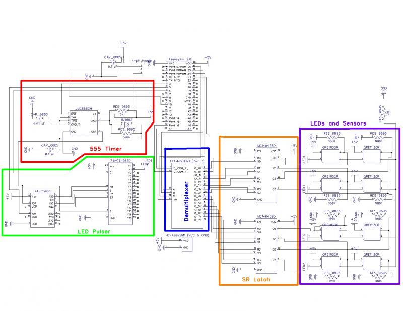
The schematic for the Bee Counter test board includes labeled functional units for ease of discussion. This test board features the same circuitry as the larger version but is simplified to include only four gates instead of forty-four, significantly...
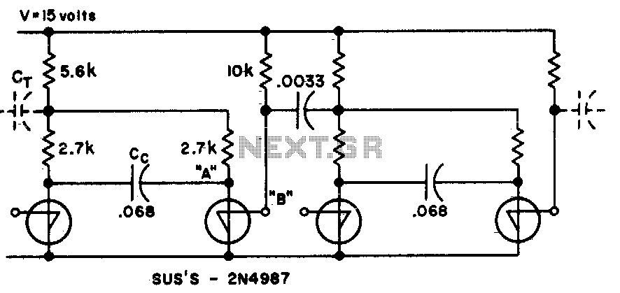
This circuit utilizes fewer components than traditional transistor flip-flops. The output at point "B" produces a transient-free waveform. The circuit in question is designed to provide a simplified approach to signal processing by minimizing the number of components involved compared...
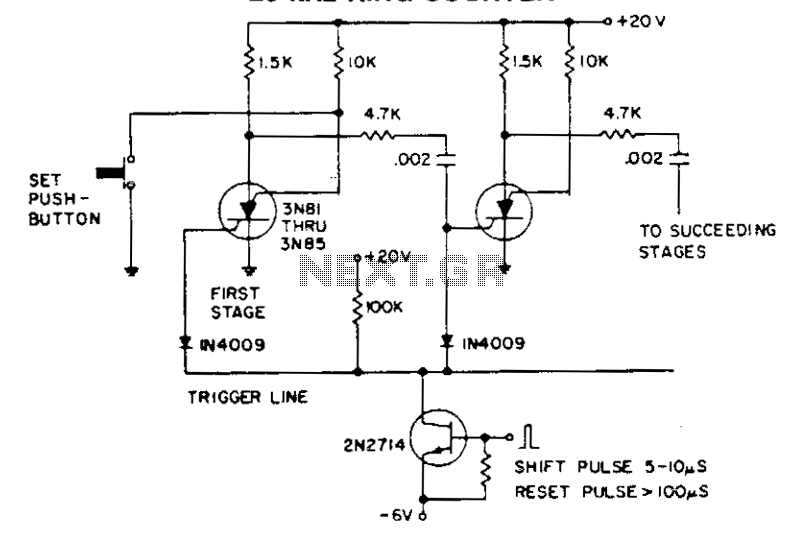
The shift pulse deactivates the conducting silicon-controlled switches (SCS) by reverse biasing the cathode gate. The charge accumulated in the coupling capacitor subsequently triggers the following stage. An excessively prolonged shift pulse charges all capacitors, resulting in the deactivation...

A simple frequency meter or frequency counter circuit featuring an LCD display and an AVR microcontroller. This includes a DIY schematic circuit diagram and embedded C code. The frequency meter circuit is designed to measure the frequency of input signals...
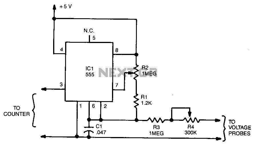
The output frequency from IC pin 3 is determined by the voltage input to pin 6. A standard frequency counter can be used to measure voltages directly over a limited range from 0 to 5 V. In this circuit,...
This circuit is a toy designed to encourage young children to count. Power is activated by switch S1, followed by closing switch S2, which causes nine LEDs to flash slowly. When S2 is opened, the LEDs turn off. Pressing...