
Bipolar Tesla Coil Radiant Energy Collector
Warning: Undefined array key "extension" in /var/www/html/nextgr/view-circuit.php on line 477
Deprecated: strtolower(): Passing null to parameter #1 ($string) of type string is deprecated in /var/www/html/nextgr/view-circuit.php on line 477

The bipolar Tesla radiant energy capture circuit is a sophisticated design that integrates various electrical components to harness radiant energy effectively. At its core, the circuit employs a bipolar Tesla coil, which allows for the generation of high-voltage, high-frequency alternating current (AC) that can be transformed into usable direct current (DC) through rectification. The graphite spark gap serves as a critical component, facilitating the discharge of energy between the two electrodes, which enhances the overall efficiency of energy capture.
The use of bifilar spiral inductors in the design is noteworthy as they are known to improve magnetic coupling and reduce losses in energy transfer. This configuration allows for the efficient transfer of energy from the Tesla coil to the rectification circuits, which include both the Villard and Greinacher quadruplers. These rectifiers convert the high-frequency AC from the Tesla coil into pulsed DC, which can be utilized in various applications, such as charging capacitors or powering low-voltage devices.
The inclusion of a supercapacitor in conjunction with a Joule thief circuit is a significant advancement in energy management. The Joule thief circuit is designed to extract energy from the supercapacitor, providing a regulated output voltage suitable for powering small electronic devices. This enhances the versatility of the overall circuit, allowing it to function in environments where conventional power sources are unavailable.
A virtual ground is proposed to improve the circuit's performance, especially in scenarios where a true ground connection is not feasible. This could involve creating a reference point within the circuit that stabilizes the voltage levels and enhances the efficiency of energy capture.
The circuit's performance is influenced by external factors, such as electromagnetic interference from nearby traffic, which can affect the amount of radiant energy captured. This highlights the importance of optimizing the design for different environmental conditions to maximize energy harvesting.
Overall, the bipolar Tesla radiant energy capture circuit represents a promising approach to harnessing ambient energy through innovative electrical engineering techniques. Further experimentation and refinement of the design could lead to significant advancements in the field of radiant energy collection and utilization.Tesla radiant energy collectors and the means of creating those apparatus. I have been working on some radiant energy designs myself, having tried the standard rectification bridge for antenna and ground, to using a greinacher voltage quadrupler rectifier, and experimenting with all the different kinds of antenna, as well as adding inductors and capacitors in various locations in my circuits. I read that one simple way to make a tesla radiant energy collector is to simply use a tesla coil with loose coupling leading to a collector circuit!Thus, my new experiment has taken to fruit, and I am proud to announce I have modified this basic building block of radiant energy transmit and capture to bring you: The bipolar tesla radiant energy capture circuit! It is a bipolar tesla coil with a graphite sparkgap bringing both the ground and top load of the standard tesla coil together.
The radiant energy circuit is loosely coupled to a bipolar tesla coil secondary! This current design I am going to show you is a mock up and collaboration of various experiments I have preformed at home. I figured that I should share the current circuit design to anybody who might be interested. It utilizes both a villard quadrupler full-wave cascade and a greinacher voltage quadrupler all tied together in parallel and sharing a common ground.
The top two inductors in the picture are bifilar spirals, and the bottom inductor is a regular air core inductor with loose coupling to condensers and then fed into a step up transformer for utilization by the radiant energy collector circuit. There is definitely work to be done here, such as a pickup coil on the secondary to help with self oscillation and a virtual ground to make the device more useful when a true ground is unavailable.
Utilizing a joule thief with JFET switching and a super capacitor to store and smooth the joule thief output could make this circuit quite useful for pulsed DC output to an inverter! I`m not clear as to what is supplying power here. Is it completely supplied from just an antenna and ground - i. e. not batteries or power supplies once caps are charged What sort of power out is it creating if you have built this already The spark gap is at the top (The two +V arrow looking labels), where the two ball-breakouts on a bipolar tesla coil would be, and they are graphite, about 2mm gap between them I`m not clear as to what is supplying power here.
Is it completely supplied from just an antenna and ground - i. e. not batteries or power supplies once caps are charged What sort of power out is it creating if you have built this already Like all of the tesla radiant energy collectors I have seen on the internet, antenna conducts to ground, either directly or indirectly; The power is coming from the secondary of the bipolar tesla coil (I. E. , Antenna), both from positive ions flowing through the wire of the secondary (Conducting indirectly to ground), thus creating a magnetic flux; Also, energy is coming from external EM sources of high potential alternating currents that interact with the air coil inductor of the secondary.
This device outputs DC from the rectification circuits (Both greinacher and villard [full-wave]) and that DC can be pulsed for use in a joule theif, etc. (With the aim of powering an LED or charging a cell phone. ). This current schematic is purely a compilation of various experiments I have worked on, I am still waiting on parts to arrive to build this specific design, although I have build one quite similar using one greinacher and one standard rectifier bridge, which self charges to one volt in about 6-8 minutes, depending on the weather and how much traffic is outside (Yes, traffic affects the capture of radiant energy!
[Presumably, big metal bodies conduct the energy away from the apparatus. ]) There is no battery, all energy flows 🔗 External reference
Related Circuits
The Testatika design, based on the Pidgeon/Wimshurst machine, represents one type of electrostatic generator that can be used to construct this system. Since the early 1900s, such power generators have significantly evolved in terms of sophistication and power output....
The delay-saving lamp circuit functions as a sound and light control delay energy-saving lighting system. It can directly replace a standard light switch without modifying the existing lighting circuits. In bright or daytime conditions, the sound control feature ensures...
Due to the low coupling coefficient, the primary self-inductance tends to short out the driving signal. However, utilizing a series/parallel set of capacitors for energy coupling increases the input impedance at resonance, thereby achieving good power transfer efficiency. The...
The American Electrician describes a glass battery jar measuring six inches by eight inches, wound with 60 to 80 turns of American wire gauge No. 18 B & S magnet wire. Inside this jar is a primary winding consisting...

When operated through a spark gap, does a Tesla coil always operate at a quarter wave, half wave, or a multiple of a whole wave, resulting in 2*n maximums? Are there sources related to creating standing waves and the...
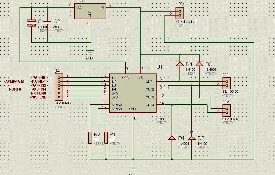
The circuit diagram includes M1 connected to Coil A of a stepper motor and M2 connected to Coil B of the stepper motor. Resistors R1 and R2 are 1 Ohm resistors used for current limiting. The circuit design involves a...