
Bipolar Stepper Motor

The circuit design involves a stepper motor controlled by two drive circuits, M1 and M2, which are responsible for energizing the respective coils, Coil A and Coil B. The stepper motor operates by sequentially energizing the coils, allowing for precise control over the motor's position and speed.
In this configuration, M1 and M2 may be transistors or MOSFETs, selected based on their ability to handle the required current and voltage levels for the stepper motor. The use of 1 Ohm resistors, R1 and R2, serves a dual purpose: they limit the current flowing through the coils to prevent damage to the motor and the driving circuits, and they also provide a means to monitor the current, as the voltage drop across these resistors can be measured.
It is essential to ensure that the resistors are rated for the power they will dissipate, calculated using the formula P = I²R, where I is the current through the resistor. The choice of a 1 Ohm resistor suggests that the application may involve high currents, thus requiring careful consideration of thermal management.
The circuit may also benefit from additional components such as diodes for flyback protection, which would safeguard the driving transistors from voltage spikes generated when the motor coils are de-energized. Proper layout and grounding techniques should be employed to minimize electromagnetic interference and ensure reliable operation of the stepper motor system.
Overall, the described circuit is a fundamental design for controlling a stepper motor, highlighting the importance of current limiting and protective measures in motor drive applications.For the Circuit diagram M1 connected to Coil A for stepper motor. M2 connected to Coil B for stepper motor. R1 & R2 1 Ohm resistors for current limiti.. 🔗 External reference
Related Circuits
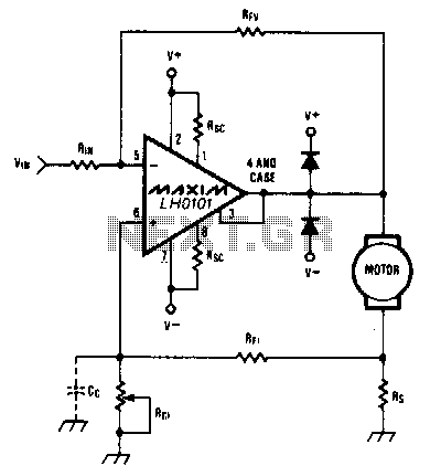
When the torque load on the motor increases, its current also rises. This increase in current is detected across Rs, and positive feedback is applied to the noninverting terminal of the LH0101, which in turn raises the motor voltage...
This simple DC servo motor circuit design can be utilized in various electronic projects. The circuit schematic illustrates that this DC servo motor driver employs a single integrated circuit along with a few external electronic components. For bidirectional DC...
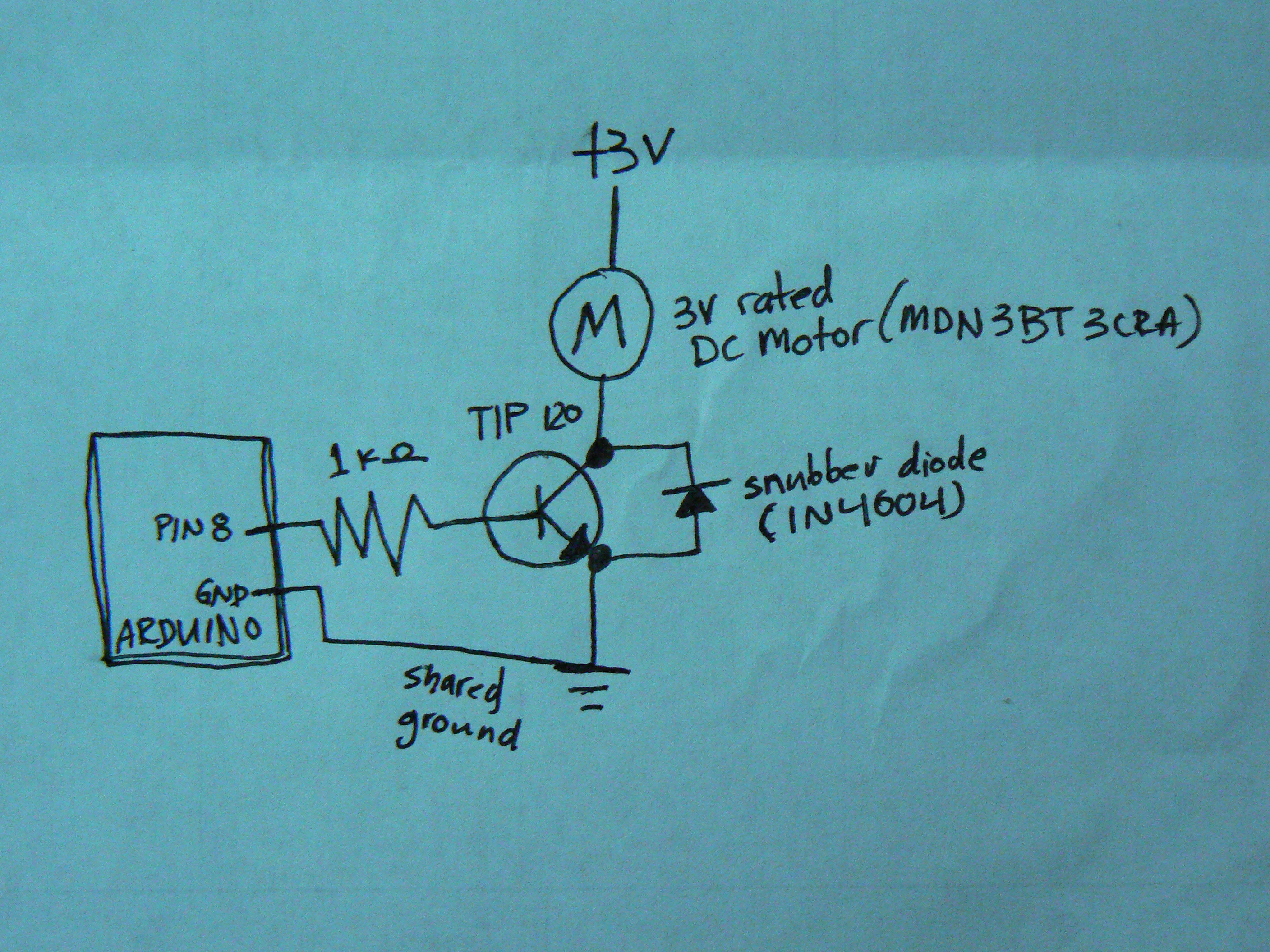
When controlling motors with a microcontroller, the snubber is quite important. This configuration is not commonly seen, as the snubber is typically placed across the motor itself. The general concept is that charge builds up on the motor coil,...
Control a small DC motor using an H-bridge with an Arduino Uno. The objective is to enable the motor to rotate in different directions based on left and right key presses on a keyboard. The provided code includes the...
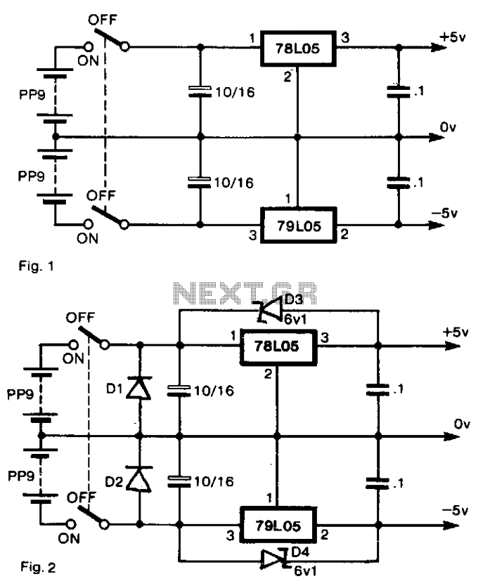
To generate regulated ±5-V supplies from a pair of dry batteries, the circuit shown in Fig. 1 is commonly utilized. To protect against inadvertent reverse connection of a battery, a diode in series with each battery would create an...

The first schematic page contains the primary content of the design, while the second page features simulation support circuitry. The primary design controls the accessory relays and indicators. It also drives the control loop and adjusts the throttle control...