
learning Arduino programming
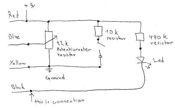
The circuit utilizes a combination of resistors and an LED to create a basic electronic setup suitable for educational purposes. The 10 kΩ resistor is typically employed to limit current flow to the LED, preventing it from burning out. The 470 kΩ resistor may be utilized in conjunction with the potentiometer to form a voltage divider, allowing for adjustable voltage levels that can be read by an Arduino analog input. The potentiometer enables students to experiment with varying resistance values, thereby understanding how changes in resistance affect current and voltage in a circuit.
The LED serves as a visual indicator, providing immediate feedback when the circuit is powered. When connected to an Arduino, students can program the microcontroller to turn the LED on and off, or even to vary its brightness based on the resistance set by the potentiometer. This hands-on experience is crucial for grasping fundamental concepts in electronics and programming, as it combines theoretical knowledge with practical application.
Overall, this circuit serves as an excellent introductory project for students to learn about the interaction between hardware components and software programming in Arduino, fostering a deeper understanding of both electronics and coding principles.The circuit consist of 10 k and 470 k resistors. Also one potentiometer resistor and led was used. This circuit is used for learning Arduino programming later in class.
In 19 March we had electronic class. All the students made simple electric circuit. The schematic of the circuit picture is above.
🔗 External referenceRelated Circuits
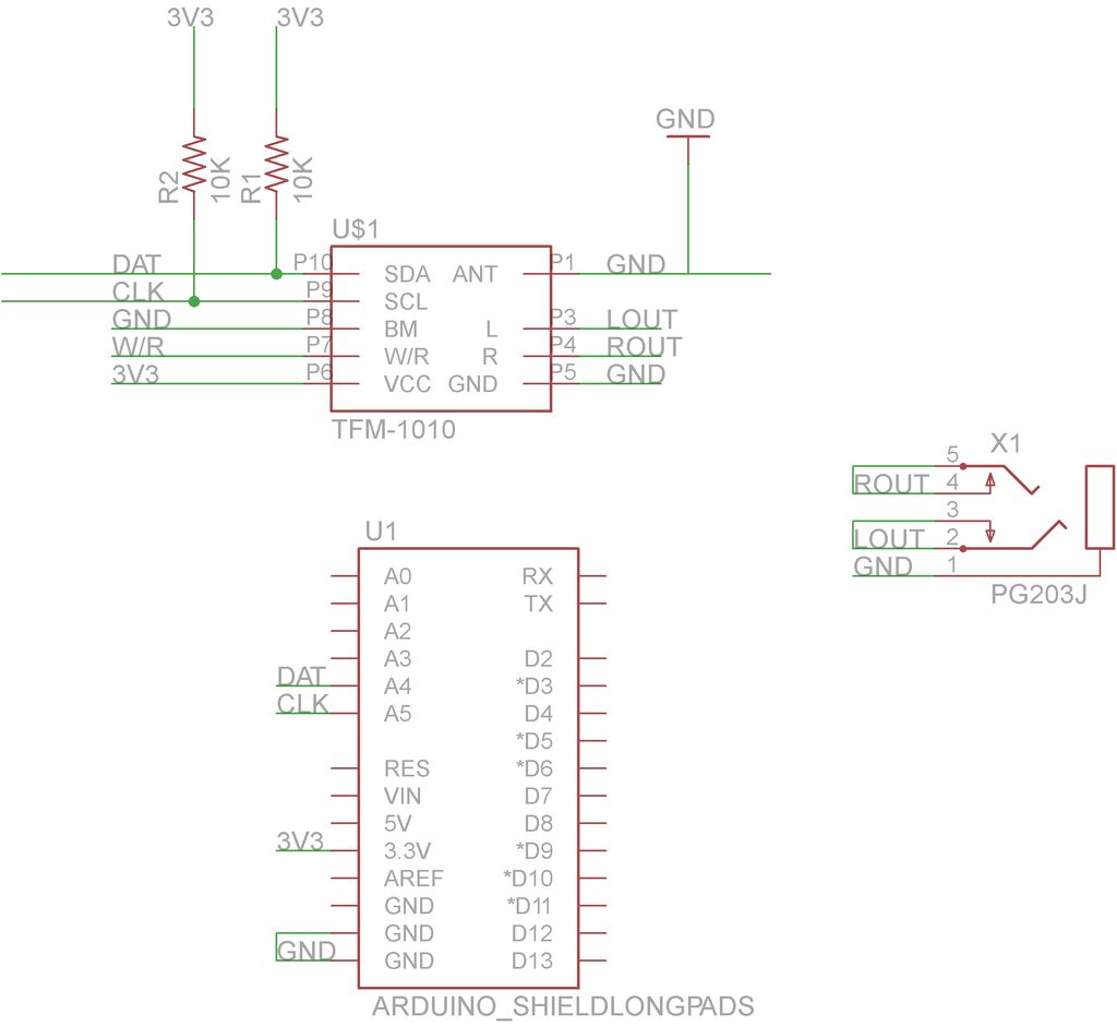
This guide will demonstrate how to construct a custom FM radio receiver shield compatible with an Arduino board. The radio chip utilized in this project is the AR1010, which can be sourced from Sparkfun or Electrokit. Code for initializing...

Basic features include an internal 512k-bit EEPROM, allowing for continuous recording and playback at any time, with long-term retention of voice data after power loss. The voice recording time is 20 seconds, and it supports segmented recording and playback....

Have you verified whether you can see the zero crossings on your input pin? It may be beneficial to write a sketch that toggles the LED on pin 13 every 50 or 60 zero crossings. This should result in...

The light is blinking instead of dimming. A specific software was used to illuminate the bulb without dimming, which includes the following code: ```cpp unsigned int i = 1; void setup() { Serial.begin(9600); ...
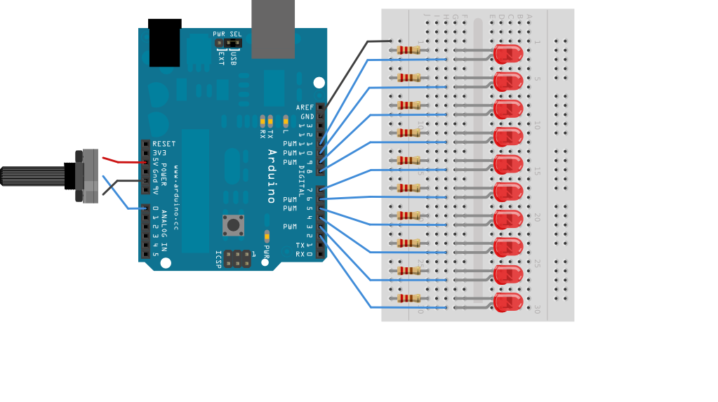
The bar graph, which consists of a series of LEDs arranged in a line similar to those found in audio displays, serves as a common hardware interface for analog sensors. It is constructed from a row of LEDs, an...
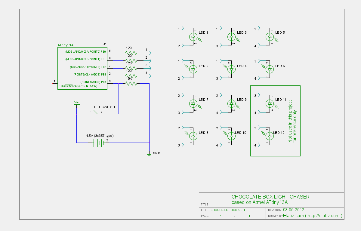
Transform a standard chocolate box into an impressive LED blinking display using an ATTiny13 AVR microcontroller, Arduino IDE, and several electronic components. The project involves creating an eye-catching LED display housed within a chocolate box. The core of the circuit...