
build your own geiger counter
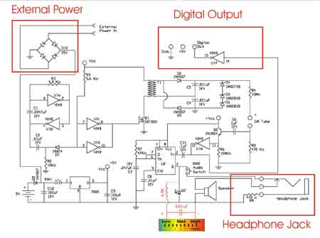
The circuit design for the enhanced Geiger counter incorporates several key components that work together to improve functionality and usability. The external power input allows for flexibility in power sources, enabling users to connect various wall transformers that meet the specified voltage and current requirements. The inclusion of the bridge rectifier converts the AC voltage from the transformer into DC voltage, which is essential for the operation of the Geiger counter. The D9 diode plays a critical role in safeguarding the internal battery from potential backflow of current when the external power is engaged, ensuring the longevity and reliability of the device.
The headphone jack serves dual purposes, allowing for audio output when headphones are connected and providing an interface for an analog meter when needed. The SPST switch integrated into the headphone jack simplifies the user experience by automatically managing the connection state, eliminating the need for manual disconnection of the speaker.
The digital output feature is a significant enhancement, providing a TTL logic pulse that can be easily interfaced with a computer. This allows for real-time data logging and visualization of radiation levels using compatible software. The unused gate from the 4049 IC is employed to generate this output signal, showcasing the versatility of the integrated circuit in expanding the functionality of the Geiger counter. Overall, these enhancements make the Geiger counter a more versatile and user-friendly instrument, suitable for various applications in radiation detection and analysis.The basic Geiger counter circuit is identical to the previous circuit. The revision is the adding of the components for our three optional enhancements; external power input, headphone jack and digital output, boxed in red. External Power – The external power is designed to allow a wide range of wall transformer to power the Geiger counter.
Wall transformers that can supply a minimum of 75 mA with voltages that range from 7-12VAC or 7-12VDC will work. The bridge rectifier is rated at 25V 1 amp. Pretty much any bridge rectifier with specifications around these specifications (or better) will work when placed inside the circuit. The positive output lead of the bridge rectifier is placed after the D9 diode. The D9 diode protects the battery when using external power. Headphone Jack – Aside of its obvious use for a headphone, this jack may also be used as a temporary output for an Analog Meter.
The headphone jack is a 3. 5mm 2-conductor jack with a SPST switch. The switch automatically disconnects the speaker when the headphone or analog meter is plugged in. Digital Output – The digital output jack provides a +5V TTL logic pulse every time a radioactive particle is detected. The digital output uses an unused gate off the 4049 as shown in the schematic. We will build a small interface between this output and a Windows PC. This will allow you to use one of the free Geiger counter graphing programs. 🔗 External reference
Related Circuits
This circuit provides a visual 9-second delay using a 7-segment digital readout LED. When the switch is closed, the CD4010 up/down counter is preset to 9, and the 555 timer is disabled, holding the output high. When the switch...
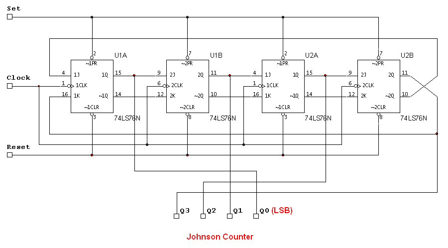
The attached schematic diagram is a Johnson Counter. Please provide advice on why "Loop 2" is considered to be invalid. Additionally, please suggest a few alternatives. The Johnson Counter, also known as a twisted ring counter, is a type of...
The circuit utilizes an Atmega8-8PU microcontroller configured for 8MHz operation with an external crystal oscillator. It incorporates a Nokia 5110 LCD and a transistor to manage the pulses generated by a reed relay. A 3.3V voltage regulator supplies power...
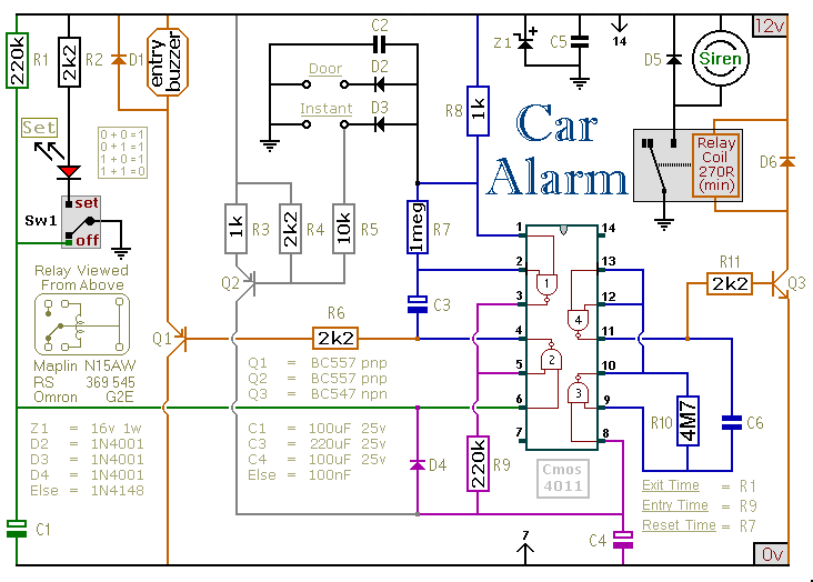
This circuit includes automatic exit and entry delays, an optional instant alarm zone, an optional intermittent siren output, and an automatic reset feature. By incorporating external relays, it is possible to immobilize the vehicle and activate the lights. For...
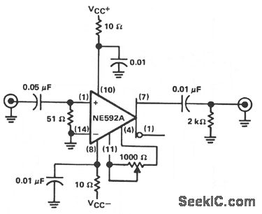
The circuit provides a voltage gain of 20 ±0.1 dB within a frequency range of 500 kHz to 50 MHz. The low-frequency response of the amplifier can be enhanced by increasing the value of the 0.05 µF capacitor connected...
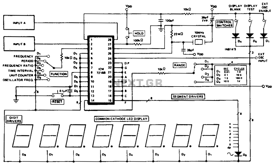
The ICM7216A can be utilized as a complete universal counter with minimal components. This circuit is capable of handling input frequencies of up to 10 MHz at INPUT A and 2 MHz at INPUT B. In cases where the...