
Build your own PC interface
The described circuit constitutes a versatile interface for amateur radio operators, enabling effective communication via digital modes. The core of the design revolves around the audio isolation transformer, which prevents ground loops and ensures clean audio signals between the PC and the transceiver. The choice of RCA sockets enhances reliability, while the use of a DIN connector simplifies connections. The optocoupler provides necessary isolation for the PTT function, allowing for safe operation of the radio equipment.
When assembling the circuit, attention must be paid to the orientation of polarized components, ensuring they are installed correctly to avoid malfunction. The layout should be designed to minimize interference and maintain signal integrity, with careful routing of shielded wires to reduce noise pickup. The enclosure should also allow for adequate ventilation and protection of the components, ensuring longevity and performance stability.
This interface serves as a bridge between modern computing capabilities and traditional radio communication, allowing users to engage in a variety of digital modes and enhancing their overall amateur radio experience.TNC and Modems ruled the world of digital communications until recently. With the advent of high speed computing and digital signal processing (DSP) all this has changed. If you own a home computer (PC) with a sound card, all you need to do is download software and obtain an interface between the PC and your radio. The interface provides the audio and digital signal level translation between the computer and the radio. Due to lack of locally available interfaces many hams imported them for large sums of money. It occurred to me that I could build an interface easily. Typically being lazy, I needed a push to get started. A swift kick in the rear would be a more appropriate term. This was provided by Miku, VU2WAP. He offered me his Rigblaster Nomic for reverse engineering. Looking inside I found a 600 ohm 1:1 audio isolation transformer for PC to transceiver mic input and presets for level control An optocoupler was used for PTT keying. On the outside there was an 8 pin mic connector or RJ45 optionally. Stereo earphone (EP) sockets for soundcard connections. A DB9 connector for RS232 PC COM port connection. To adapt to various brands they provided internal jumpers. The isolation transformer was the most critical part of the equipment. It was the hot topic of discussion with my friends on 14. 130Mhz including Zal VU2DK, VU2DAD Dev VU2NTT Neeraj, VU2WAP Miku. This transformer is not commercially available in the electronics market. Initially I used one salvaged from modem cards but this was not acceptable if many units were to be made.
I designed one taking many parameters into consideration and had it fabricated locally. If you want to make your own it is simple, buy a driver transformer used in 6V L type transistor radio plate. Dissemble and strip its windings. Wind 1500 turns primary and 1500 turns secondary with 44 SWG wire. Assemble it back. Purist may also add a layer between the two windings and ground one end to make a Faraday shield. The next item was the opto coupler 4N33 with Darlington pair transistors in its output. (The 4N35 is more commonly available, it can be used with an additional 2N2222 to boost the output current and gain.
) Considering that we are ham fisted and the VU market has flimsy EP connectors, I decided on using commercially available 6 x RCA sockets used in VCD players. The 8 pin Mic connector was replaced with a more readily available PC keyboard connector 5 pin DIN. The 9 pin D shell is common so I retained it. Instead of PCB jumpers, I left it to the home brewer to hardwire the connections with shielded wire. i. e. With shield going to respective grounds. As I feel this method is simpler and every home brewer will at least have this much information about his rig.
Do not be tempted in using keyboard lead with 5 pin DIN connector molded, these are prone to Hum pickup. Use two lengths of single core shielded wire for respective connections. The drawing has all the details of PCB, schematics and component layout. Assemble it according to details provided. Take care with polarized components like diodes optocoupler etc. Mount all sockets on the PCB. Finally dont forget to put the PCB in a good looking box if you want everyone to appreciate your handy work.
You do not need this interface to receive. Simply hook up a lead from your rig to PC sound card and start receiving. Connect the line in on Interface to out of sound card. Connect PC speakers to line out on interface. Optionally you may also connect your headphones to phones socket on interface. Keep Mic level control at 75% level with some spare margin to adjust. Check all your work carefully, hook up the interface to your rig and PC. Install the software switch on and tune, adjust the sound levels on PC as well as the interface for clean signal. Monitor various QSOs till you get the hang of things. Join the fun. With the unit supporting so many modes like PSK31, MFSK16, MT16, Hellschr 🔗 External reference
Related Circuits
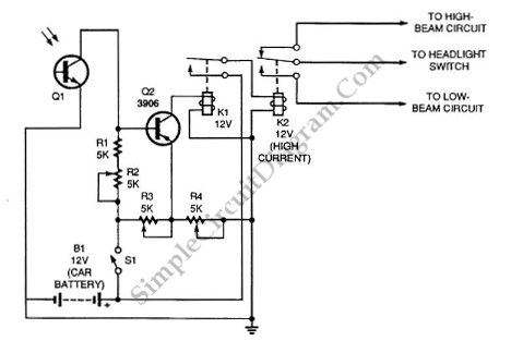
Automatic headlight dimmer circuit diagram for a car's headlight. This circuit ensures maximum brightness for optimal visibility while automatically switching when necessary. The automatic headlight dimmer circuit is designed to enhance driving safety by adjusting the brightness of the vehicle's...
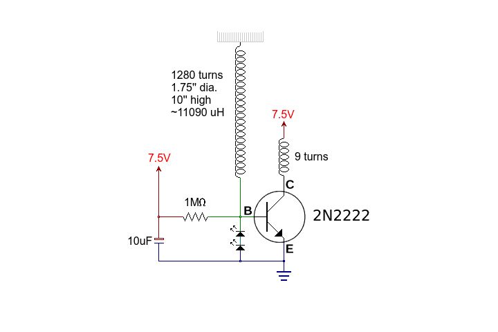
This circuit is straightforward. The accompanying graphics and images provide all necessary details. After gathering all materials, connect the transistor according to the provided schematic. The circuit in question is a basic transistor circuit that serves as an introductory project...

A capacitor step-down DC power supply circuit is presented. This circuit eliminates the need for power transformers, utilizing capacitive voltage drop rectification and regulation, which significantly reduces the overall size of the circuit. The circuit includes a capacitor step-down...
The circuit schematic is straightforward. Information regarding the assembly and testing of circuits is not provided, as there are many instructional resources available. The circuit schematic in question is designed to be simple and user-friendly, allowing for ease of understanding...
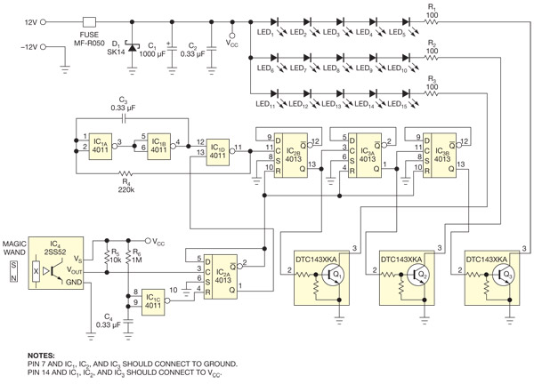
This circuit enables the activation of holiday bulbs with a wave of a magic wand. The strings of lights flash in a sequential manner. The core concept relies on a magnet. The circuit operates by utilizing a magnet as the...
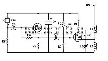
This is a low-cost and easy-to-build low-powered FM transmitter. The range of the FM transmitter is claimed to be about 300 feet when operating at a 9V supply. The range is said to increase to approximately 400 feet when...