
Doorbell Cascade
To implement the addition of a second doorbell, a comprehensive understanding of the existing doorbell circuit is essential. The typical doorbell system consists of a transformer, a push button, and a chime. The transformer converts the standard household voltage (usually 120V AC) to a lower voltage (typically 16V AC) suitable for the doorbell system.
In the proposed modification, the circuit needs to accommodate a second push button and chime without disrupting the functionality of the original doorbell. This can be achieved by wiring the second push button in parallel with the first one. When either button is pressed, the circuit will complete, allowing current to flow to the chime.
The installation involves the following steps:
1. **Power Supply**: Ensure the transformer can handle the load of both doorbells. If the existing transformer is rated for a lower wattage, it may need to be replaced with one that has a higher capacity.
2. **Wiring**: Use 18 AWG doorbell wire for the connections. Run a wire from the transformer to both push buttons, connecting them in parallel. This means that both buttons will share the same power source.
3. **Chime Connection**: Connect the output from both push buttons to the chime. The chime should also be compatible with the voltage provided by the transformer.
4. **Testing**: After completing the wiring, test each button individually to ensure that the chime activates correctly from both locations.
5. **Mounting**: Securely mount the second push button in the desired location, ensuring it is easily accessible.
By following these guidelines, the installation of a second doorbell can be accomplished efficiently, enhancing the functionality of the existing doorbell system.Sometimes you have to do it the hard way, even if doing it the easy way is an option. That is the case here. The intention is to add a second doorbell in.. 🔗 External reference
Related Circuits
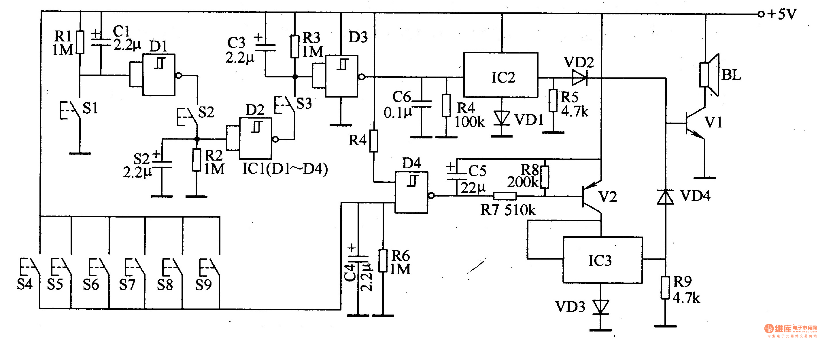
The password electronic doorbell circuit comprises a trigger circuit and a music generating circuit, as illustrated in Figure 3-119. The trigger circuit includes buttons S1-S9, four NAND gate Schmitt trigger integrated circuits (IC1), and external RC components. The music...
This circuit will light a lamp at a remote location when the doorbell switch is pressed. This circuit should only be used with the solenoid type doorbells; the electronic type that play tunes will not work here. It is...

This simple and cost-effective ding-dong electronic doorbell circuit is based on IC 8021-2. The IC has an integrated circuitry that generates a ding-dong sound each time its pin 3 is pulled low. The sound is stored in the IC...
This circuit provides a delayed visual indication when a door bell switch is pressed. In addition, a DPDT switch can be moved from within the house which will light a lamp in the door bell switch. The lamp can...

This 6V battery-operated doorbell light circuit can be connected in parallel with any existing AC 230V doorbell. When the doorbell switch is pressed, the bell sounds as usual, and the AC mains supply available across the doorbell is routed...

This is a circuit design for a doorbell that produces a bird-like sound. The circuit is controlled by an NPN transistor. The operation of the circuit begins when P1 is set to an experimental value, starting with approximately 220...