
Car Parking Sonar
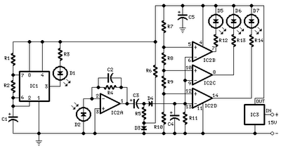
The burst is generated by the oscillator built around U4D, which must be set to 40 kHz using TR2 for maximum sensitivity. U4E buffers the output, while U4F boosts the signal, effectively doubling the voltage span across the TX piezo transducer. A new burst is generated each time the decade counter (4017) in the circuit diagram is in its reset state, selecting output 0. The other outputs (1 to 9) are scanned sequentially following burst generation until an echo is detected by the RX receiver. The received echo is then amplified by the transistor input stage, triggering a monostable circuit built around U4A and U4B. This monostable temporarily halts scanning, and the LED corresponding to the obstacle distance remains continuously lit. The buzzer emits a beep when the first LED (indicating minimum distance) is lit. Care should be taken not to confuse the ultrasonic transmitter with the receiver, as they appear very similar; marking them clearly upon purchase is advisable.
During setup, the ultrasonic transducers should be placed on a soft surface near the edge of a table, positioned 10 cm apart and pointing outward. TR1 and TR2 should be adjusted using a rigid surface (e.g., a metal sheet) placed at a variable distance in front of the sensors. It is important to ensure that the sonar system is installed in a suitable enclosure beneath the car's rear bumper, using a plastic case that is not too small. The transducers should be separated by 7-10 cm and surrounded by sound-absorbing material to prevent the receiver from detecting direct sound instead of the reflected sound. Additionally, the transducers should not be mounted in direct sunlight or exposed to rain.
TR2 should be set for maximum sensitivity, typically 40 kHz for most commercially available ultrasonic transducer pairs, while TR1 should be adjusted for the desired range, with minimum resistance shortening the distance for each LED (minimum range). A suggested range is 90 cm (10 cm per LED). Once the monostable circuit expires, scanning resumes, restarting the send-and-listen sequence. If no echo is received, the scanning continues, and all the LEDs remain slightly lit.Tihs circuit has: automatic switch on on rear gear. led-bargraph display. audible bleep on last led. "good old" design style, no microcontrollers! Based on an ultrasonic amplifier from an article seen on a 1982 magazine, it was once installed on the rear bumper of my Volvo Station Wagon. It served very well for many years. Connecting it to the reverse gear lights, it switches on automatically and shows you the distance to the nearest obstacle (according to his beam) on a led scale.
When the last led lights, a buzzer is also activated telling you to stop immediately. It works on the sonar principle, sending an ultrasound burst and listening for first echo. The burst generated by the oscillator built around U4D (you must set the frequency using TR2 to have 40 kHz or the maximum sensitivity), U4E buffers the output and U4F boost the signal doubling the voltage span across the TX piezo transducer . A new burst is generated each time the decade counter (4017 in the circuit diagram) is in its reset state, that is output 0 is selected.
The other outputs (1 to 9) are scanned sequentially following burst generation, until an echo strikes back the RX receiver. It is then amplified by the transistor input stage, triggering the monostable built around U4A - U4B.
The monostable stops temporarly the scanning, and a led corresponding to the obstacle distance appears as continuously lit. The buzzer bleeps when the first led (minimum distance) il lit. First of all, be careful not to exchange the ultrasonic transmitter with the receiver: they look very similar, and I suggest you to mark them very clearly from the moment you buy them.
During setup, place the ultrasonic transducers over a soft surface, near the border of a table, 10 cm apart of each other pointing outwards the table. Then adjust TR1 and TR2 using a rigid surface (for example a metal sheet) placed in front of sensors, at a variable distance.
I enjoyed the sonar for many years. It was installed below the car's rear bumper in a plastic case. Do not choose an enclosure too small: always separate the transducers by 7-10 cm and plenty of sound-absorbing material, otherwise the receiver will reveal the direct sound instead of the reflected one. The same applies if the sound travels through a rigid fixture, so it is a good idea to fix them with separated supports.
And remember not to mount the tranducers exposed to direct sunlight nor rain. Set TR2 for maximum sensitivity (usually 40 kHz for most commercially available ultrasonic transducer pairs). Set TR1 for your preferred range. Setting it to minimum resistance shortens the distance for each led (minimum range). I suggest a range of 90 cm (10 cm each led). When the monostable expires, scanning is resumed and restarting the send-and-listen sequence. If no echo is received, the scanning never stops and all the leds are slightly lit. 🔗 External reference
Related Circuits
During rainy seasons, it can be quite bothersome when the car wipers operate continuously without pause. Have you ever considered implementing speed control for the wipers? While there are wiper control modules available commercially, many of them can be...
All distances mentioned can vary depending on the infrared transmitting and receiving LEDs used and are significantly affected by the color of the reflecting surface. Black surfaces greatly reduce the device's sensitivity. This circuit can also be applied in...
A car battery deteriorates in use, and its life seldom exceeds four years. When new, its voltage may drop to only 2V while cranking the engine. A car battery, typically a lead-acid type, is essential for providing the necessary electrical...
This is a diagram of a car audio active loudspeaker utilizing the LF353 operational amplifier from National Semiconductor. For optimal performance, the NE5532 is recommended to split the audio signal into three frequency bands using an active filter. The...
In Fig.1 see a DC current sensing switch, in which the current is applied from an 8 to 16 Volt supply. The R1 value is chosen so that it generates roughly 100 mV at the required trip current. In...
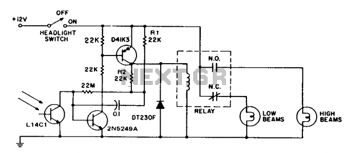
This circuit switches car headlights to the low beam state when it detects the lights of an oncoming vehicle. The received light is of low intensity and highly directional, indicating the use of a lens with the detector. A...