
BCD to Decimal Converter Circuit
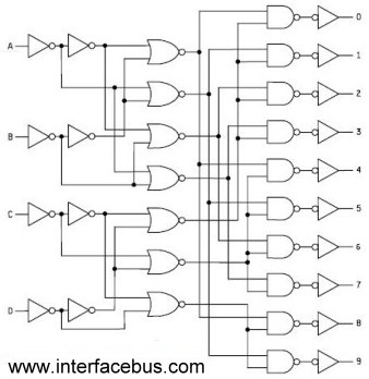
The Binary Coded Decimal (BCD) to Decimal conversion circuit is designed to facilitate the translation of a 4-bit BCD input into its corresponding decimal output. This circuit employs standard glue logic ICs, which are versatile and can operate across different logic families as long as they share compatible voltage levels. The circuit's architecture typically includes a BCD to Decimal Decoder, which takes the 4-bit BCD input and generates a corresponding active low output for decimal values ranging from 0 to 9.
The truth table for the BCD to Decimal Decoder outlines the active low outputs for each BCD input combination. For instance, when the BCD input is 0000, the output corresponding to decimal 0 is active low, and similarly, for BCD 1001, which represents decimal 9, the output for 9 is also active low. Inputs beyond the BCD range (i.e., 1010 to 1111) result in all outputs being high, indicating that the circuit is not designed to process these values, thus maintaining output stability for inputs exceeding 9.
The circuit's design allows for seamless integration of various logic families. The operational characteristics of the circuit remain consistent across different IC series, such as the 74xx and 54xx series, with the primary difference being the temperature range specifications. This flexibility in design makes the BCD to Decimal conversion circuit adaptable for various applications in digital electronics.
In addition to the BCD to Decimal Decoder, a Decimal to BCD Encoder can be utilized to convert decimal numbers back into their BCD representation, showcasing the bidirectional nature of number representation in digital systems. The circuit's design can also be represented in multiple forms, allowing for different implementation strategies while achieving the same functional outcome of translating a 4-bit BCD code into a 9-bit binary code. This versatility is essential in digital logic design, where different configurations may be preferred based on specific application requirements.Binary Coded Decimal is a number system that only counts from 0 to 9 and then repeats. The table below shows the conversion between the different numbering systems and BCD code. BCD is also called 8421 because the binary LSB counts as a 1, the next bit adds 2, than 4 and the final MSB bit adds 8 to the final numbers. So a BCD 1001 is equal to 8 plus 1 or decimal 9 [as the table shows]. Circuit to convert Binary coded decimal to decimal. Using standard glue logic ICs; note the circuit works regardless of the particular logic standard used, as long as those families can communicate with each other over the same voltage levels. Manufacturers of Standard Glue Logic The true table for the BCD to Decimal Decoder is shown above. The output is active low and counts from 0 to 9 decimal. When all BCD inputs are low `0`, output 0 is low and so on. Note that this circuit only counts to 9, so any input higher than `9` results in all the outputs going high.
So even as the inputs continue to change the output remains unchanged in the last six entries. Functionality there is no difference between a 74xx part and a 54xx part. The difference between a 74x and 54x part is their Operating Temperature Ranges. Also refer to a Decimal to BCD Encoder [Binary coded decimal decoder]. There are a number of different ways to represent a logic function. The circuit above shows a different representation than the circuit at the top of the page. Regardless of the logic function the circuit translates a 4-bit BCD code into a 9-bit Binary code. 🔗 External reference
Related Circuits
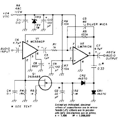
An audio signal applied to VI is passed through the operational amplifier 741, U2. After being amplified, the output signal V2 is sampled and applied to a negative voltage doubler/rectifier circuit composed of diodes CR1 and CR2, along with...
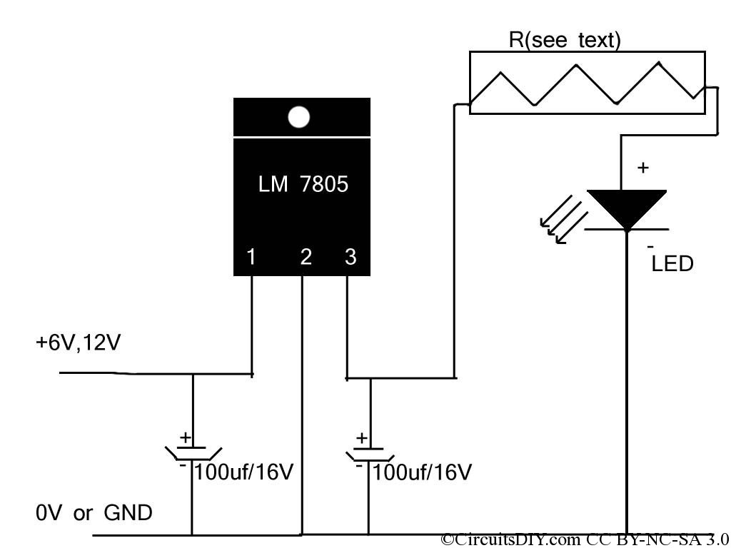
If the reader arrived here via Google, they may have encountered other circuits for high-power LED driving that include many components such as inductors, operational amplifiers, various regulator ICs, transistor feedback networks, and microcontrollers. While those circuits tend to...
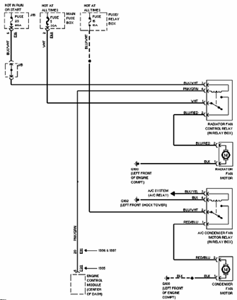
The 1996 Suzuki Esteem Cooling Fan system includes a control relay for the radiator fan (located in the relay box), air conditioning fan motor, radiator fan motor, condenser fan motor, junction box, fuse and relay box, and engine control...
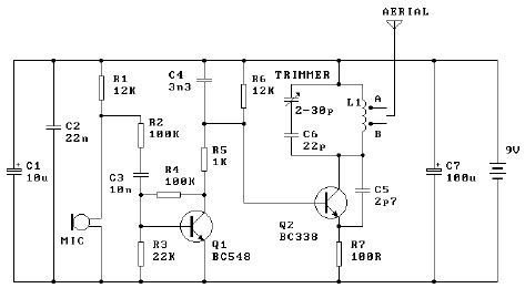
The tuned coil L1 has two output tap points for the antenna connection, labeled "A" and "B." Both outputs are low-level, allowing the user to select between a stable low range or a more unstable but higher range. Tap...
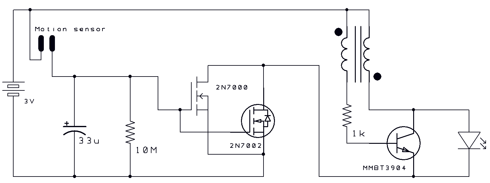
Two thoughts on a motion-activated Joule Thief LED bike light. The circuit for switching on and delayed switch-off is simple. The motion-activated Joule Thief LED bike light utilizes a straightforward circuit design that capitalizes on the principles of energy conservation...
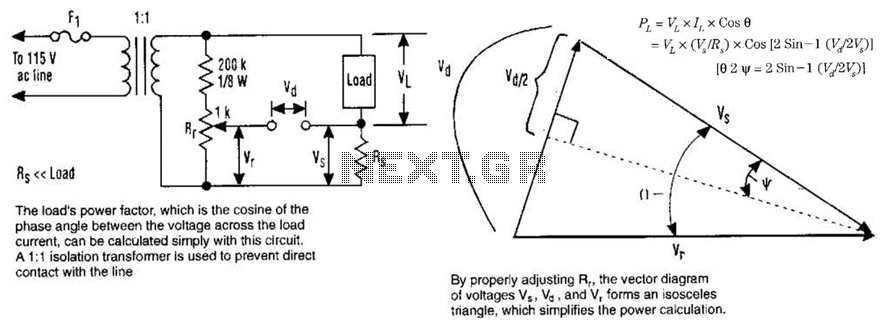
The load's power factor, defined as the cosine of the phase angle between the voltage across the load and the load current, can be calculated using this circuit. An isolation transformer with a 1:1 ratio is employed to prevent...