
Constant Temperature Circuit
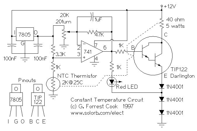
The constant temperature circuit described is designed to maintain a stable temperature in various applications, utilizing low power consumption to enhance efficiency. The primary components of this circuit typically include a temperature sensor, such as a thermistor or thermocouple, an operational amplifier (op-amp), and a control element like a relay or a transistor to regulate heating or cooling devices.
In operation, the temperature sensor continuously monitors the ambient temperature and sends a voltage signal to the op-amp. The op-amp compares this signal against a predefined reference voltage that corresponds to the desired setpoint temperature. When the sensed temperature deviates from the setpoint, the op-amp's output changes, triggering the control element to activate or deactivate the heating or cooling mechanism.
To improve stability and response time, feedback mechanisms can be incorporated, allowing for adjustments based on the rate of temperature change. Additionally, hysteresis may be applied to prevent rapid switching of the control element, which can lead to wear and tear or inefficiencies.
The circuit can be tailored for specific applications by selecting appropriate components and tuning parameters such as gain, setpoint, and response time. This versatility makes it suitable for use in various fields, including HVAC systems, laboratory equipment, and industrial processes where precise temperature control is essential.Constant Temperature Circuit. (C) G. Forrest Cook 1997 Introduction This circuit is a generic low power temperature controller that can be used for stabilizing temperature. 🔗 External reference
Related Circuits
Continued from the previous post. The same principle is true for the following: temperature to current transmitter. In this case, the input voltage is proportional to the measured temperature, not the rotation. The temperature input is a full analog,...
This circuit is designed to drive an ultrasonic transducer. A question has arisen regarding how to limit the output current, as a 60W transducer may be at risk of damage due to excessive current. Guidance or examples for integrating...
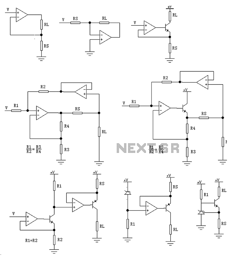
The circuit is designed to provide several constant current outputs to the load resistor RL. The first RL is floating and is rarely utilized. The second RL serves as a virtual ground and is not commonly used either. The...
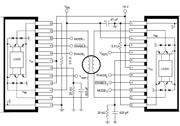
The A3952S stepper motor controller, designed by Allegro MicroSystems, can be utilized to create a straightforward and effective motor driver circuit suitable for various electronic applications. This controller supports continuous output currents of up to 2 A and operates...
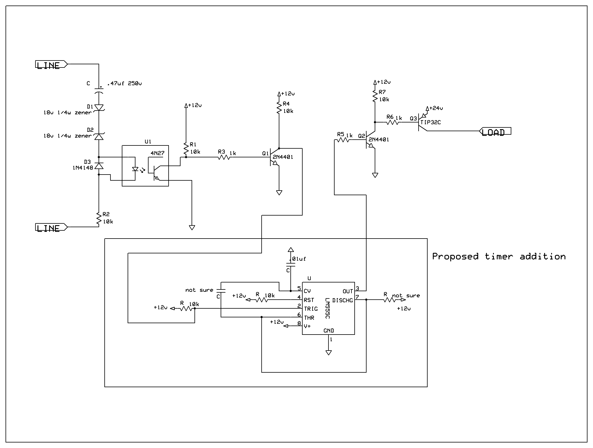
A ringer interface circuit is designed to buffer the output of a central telephone system, which connects to multiple ringers distributed throughout a building. This circuit addresses an issue where the line overloads when ringing, requiring a reset. The...
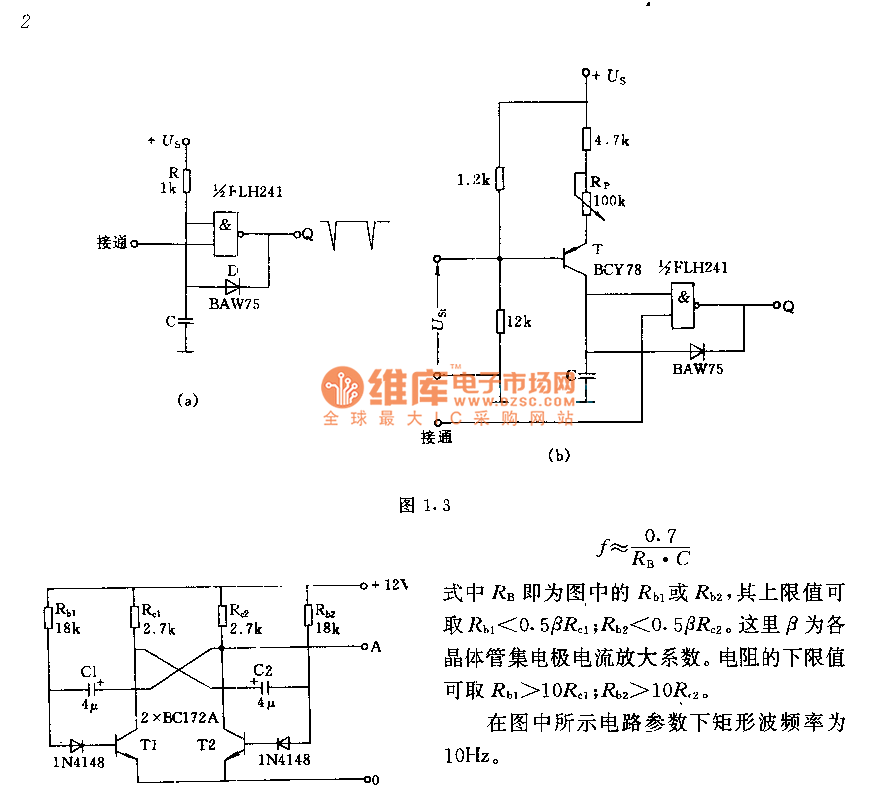
The circuit consists of two components whose parameters and models are designed to simultaneously generate a rectangular wave with a duty cycle of 1:1. The frequency is defined by the equation f = 0.7/(RB * C), where RB refers...