
The converter IC circuit diagram

The TDA8444 serves as a crucial component in audio and signal processing applications where the conversion of digital audio signals to analog form is required. Its architecture allows for precise control over audio output characteristics, making it suitable for use in various consumer electronics, including televisions, audio receivers, and multimedia devices.
The 16-pin configuration of the TDA8444 includes pins designated for power supply, ground, digital input signals, and analog output. Each pin's function is critical for ensuring proper operation and integration into larger systems. For instance, the digital input pins receive binary data that represents audio signals, while the output pins provide the corresponding analog voltage levels, which can be fed into amplifiers or other analog processing circuits.
In a typical application circuit, the TDA8444 interfaces with the LM1036N, an audio control IC that manages volume and tone adjustments. The CPU plays a vital role in this configuration, sending control signals to both the TDA8444 and the LM1036N to adjust audio parameters dynamically. This integration allows for enhanced user experience, as adjustments can be made in real-time based on user input.
The application circuit often includes additional components such as resistors, capacitors, and possibly operational amplifiers to filter and condition the output signals. The layout of the circuit should be designed to minimize noise and interference, ensuring high-quality audio output. Proper attention to power supply decoupling and grounding techniques is essential to maintain the integrity of the analog signals produced by the TDA8444.
Overall, the TDA8444 is a versatile D/A converter that, when combined with appropriate control circuitry, provides an effective solution for digital audio applications, allowing for high-fidelity sound reproduction.TDA8444is the D / A ( digital / analog ) converter IC produced by Philips, and it is used to convert digital signals to analog signals. 1. pin functions and dataTDA8444 IC uses 16-pin double-row package, andpin functions and data are shown in Table 1.
2. Typical application circuitTDA8444 and LM1036Nare matched byCPU to control the tone, volume,two-channel electronic balance. The the typical application circuit isshown in Figure 1. 🔗 External reference
Related Circuits
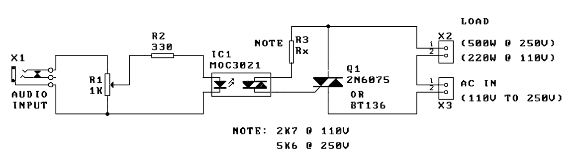
A music-to-light modulator is a circuit which controls the intensity of one or more lights in response to an audio input. The problem in older circuits is that there was a direct electrical connection between the lights using mains...

Connect the components, ensuring to pay attention to the connections for the transistor. The 22-ohm load resistor and thermistor should be connected in a manner that allows for good thermal contact. Note: If using the Light Application Adapter, REFIN-...
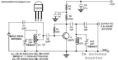
The coil L2 is tapped at the first turn from the ground lead side and is similar to coil L1, but consists of only three turns. The pin configuration of the transistor 2SC2570 is illustrated in the FM antenna...
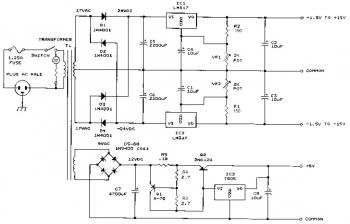
This bench power supply features three solid-state DC power supplies. The first supply provides an output of 1.5 to 15 volts at 1 ampere. The second supply offers a range of -1.5 to -15 volts at 1 ampere. The...
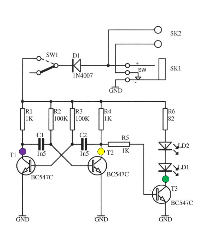
The schematic circuit presented below illustrates an infrared transmitter. The infrared beam is emitted in a nearly line-of-sight manner towards another device equipped with an infrared receiver. The displayed waveforms represent the output voltages from two intermediate stages (purple...
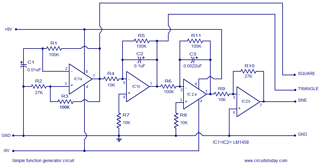
A simple function generator circuit utilizing the LM1458 is presented here. The LM1458 is a dual general-purpose operational amplifier. The two op-amps within the LM1458 share a common bias network and power supply line, yet operate independently. The function generator...