
basic transistor circuits for beginners explored

The compilation presents several fundamental transistor circuits that serve as essential building blocks for beginners in electronics. The current amplifier circuit utilizes NPN transistors to amplify input current, demonstrating the principle of transistor operation in signal processing. The configuration typically includes a biasing network to set the operating point of the transistors, ensuring linear amplification within a specified range.
The current limiter circuit employs two NPN transistors along with resistors to regulate the output current, protecting the circuit from excessive current conditions. This configuration is particularly useful in power supply applications where overcurrent protection is critical. The design often incorporates feedback mechanisms to maintain stability and responsiveness to load changes.
The oscillator circuit demonstrates the ability of transistors to generate periodic signals. By connecting two NPN transistors in a feedback loop with passive components such as resistors and capacitors, the circuit can oscillate at a frequency determined by the component values. This type of circuit is fundamental in applications such as clock generation and signal modulation.
Lastly, the electronic latch configuration is a pivotal example of bistable multivibrator circuits, which can maintain a stable state until an external input changes it. This circuit is useful in memory applications and digital logic systems, where it can store binary information. The latch typically consists of two cross-coupled transistors, allowing it to maintain its state until deliberately reset or toggled by input signals.
Overall, the described circuits exemplify the versatility and utility of transistor configurations in basic electronic designs, providing a practical foundation for further exploration in the field.This article is the compilation of small transistor circuits and configurations for beginners like current amplifier and limiter, oscillator, latch etc. Using just a couple of NPN transistors a simple current amplifier circuit can be built. Two transistors and resistors can be connected together to form a versatile current limiter circuit. The oscillator is formed when two transistors and a couple of passive components are connected. Another simple yet important configuration of transistors in the form of an electronic latch is shown in the diagram alongside..
🔗 External reference
Related Circuits
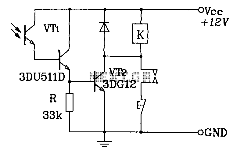
A Darlington phototransistor serves as the primary component for the photoelectric function within a self-locking control relay circuit. The circuit utilizes a Darlington phototransistor, which is known for its high current gain and sensitivity to light. This device is configured...
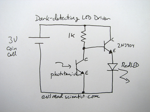
A circuit that uses a phototransistor to create a light-sensitive switch. When there is no light in the room, the LED connected to the phototransistor lights up, and when there is light, the LED turns off. Any schematic or...
Over 1400 top electronics projects and electronic circuits with photos, datasheets, and easy-to-read schematics, along with explanations of how they work and how to build them. The collection comprises a vast array of electronics projects suitable for enthusiasts and professionals...
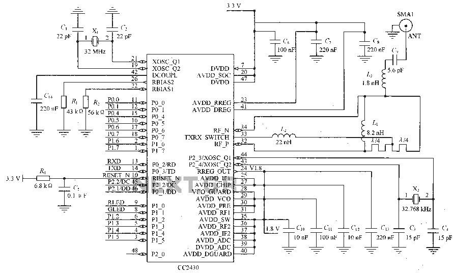
Figure C1 and C2 depict a 22 pF capacitor connected to a 32 MHz crystal oscillator circuit, which utilizes a quartz crystal for standard operation. Capacitors C3 and C4, each rated at 15 pF, are connected to a 32.768...
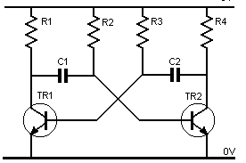
Assume one of the transistors, TR1, becomes conductive initially. Under this condition, the collector-emitter voltage of TR1 should ideally be zero; however, it will be approximately 0.1 volts, while the base-emitter voltage is +0.6 volts. As a result, capacitor...
Here the popular 555 timing IC is wired as a monostable. The timing period is precise and equivalent to: 1.1 x R1 x C1. With component values shown this works out at approximately 1.1 msec. The output duration is...