
h bridge circuit
An H-bridge circuit is essential in applications requiring bidirectional control of DC motors. The configuration typically includes four switching elements, which can be either bipolar junction transistors (BJTs) or field-effect transistors (FETs). The arrangement of these transistors allows for two complementary paths for current to flow through the motor, enabling it to rotate in either direction based on the control signals applied to the gates or bases of the transistors.
The H-bridge operates by activating two diagonally opposite transistors while keeping the other two off, allowing current to flow through the motor in one direction. To reverse the motor's direction, the control signals are switched to turn off the first pair of transistors and turn on the other pair. This method of control provides a straightforward solution for applications such as robotics, where precise motor direction control is necessary.
It is crucial to select appropriate transistors that can handle the maximum current the motor may draw during operation. For small motors, standard transistors may suffice; however, for larger motors, higher-rated components or additional protective measures, such as heat sinks, may be required to prevent thermal damage. Additionally, implementing flyback diodes across the transistors can protect the circuit from voltage spikes generated when the motor is turned off, thus enhancing reliability.
In summary, the H-bridge circuit is a fundamental building block in motor control systems, providing an efficient means to manage motor direction with minimal complexity while requiring careful consideration of component ratings to ensure safe and reliable operation.An H bridge is a kind of circuit you use to control the direction (and sometimes speed) of an electric motor, using only a single polarity voltage (you need to reverse the way current flows in order to reverse the way the motor rolls). You have 4 transistors, wired as ON OFF switches. Two signal lines allow you to run the motor in one direction, w hen reversed, the motor runs in the other direction. It`s very straightforward to use and build, but be careful to use only small motors, as the currents drawn from the bigger types can burn your components. 🔗 External reference
Related Circuits
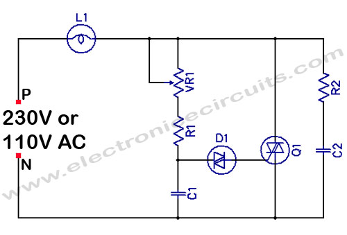
Filament Light Dimmer Circuit. This simple triac dimmer can be used to control incandescent filament lamps up to 200W. The circuit operates on standard AC voltage. The filament light dimmer circuit utilizes a TRIAC to control the power delivered to...
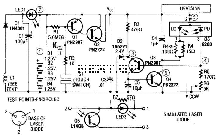
A laser diode TOLD9200 (Toshiba) serves as a source of laser light. Q3, Q2, and SI constitute a touch switch to control the laser. L1 is an RF pickup coil designed to extract energy from an RF-type battery charger....
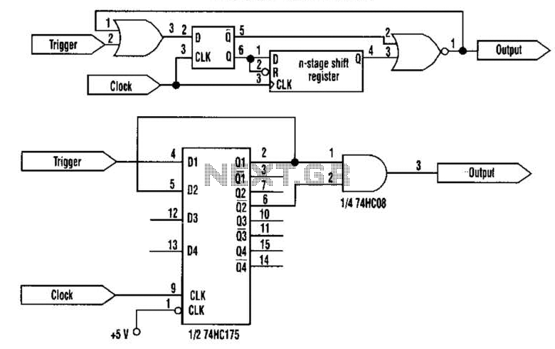
This approach utilizes a Hip-Hop, a shift register, and two gates (A). Before the one-shot pulse, the output of the NOR gate is 0. Consequently, the data input of the D-type flip-flop is equivalent to the trigger. When a...
The crystal radio derives its name from the galena crystal (lead sulfide) utilized for rectifying signals. A "cat's whisker" wire contact was adjusted on the crystal's surface until a diode junction was established. The 1N34A germanium diode serves as...
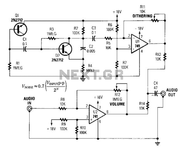
By introducing a small amount of noise to a signal intended for digitization (approximately 0.7 bits), where n represents the number of bits, for instance, an 8-bit signal with a peak-to-peak voltage of 2 V would result in a...
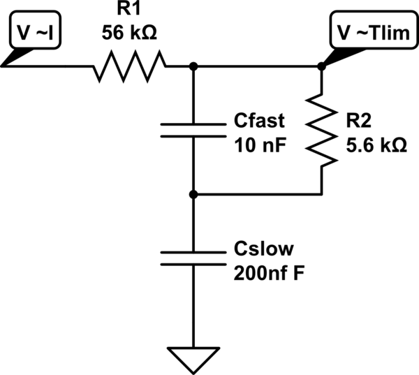
A MOSFET is employed to drive a load that includes a sense resistor in its current path. The voltage across this resistor is utilized to trigger a circuit capable of disconnecting the load in the event of an overcurrent...