
lg tv circuit diagram
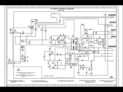
No description available.
Related Circuits
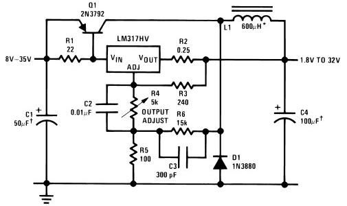
The circuit diagram of this LM317 power supply electronic project requires a few external components. The input voltage for this project must be between 8 and 35 volts, providing a variable output voltage ranging from 1.8 volts to 32...

This circuit represents a negative resistance configuration. All previous circuits utilize RC time constants to achieve resonance. LC combinations can also be employed, providing good frequency stability, high Q factor, and rapid startup. In this circuit, a signal input...
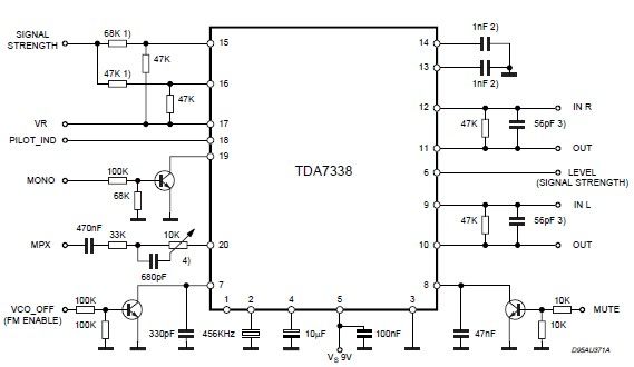
The pilot detector output is configured as an open collector output, necessitating the use of an external pull-up resistor. To set the decoder to "MONO," Pin 19 must be clamped to a voltage lower than 0.8V. The open collector output...
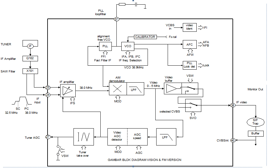
This section is designed to amplify the signal until it reaches the required level. The IF amplifier is equipped with an Automatic Gain Controller (AGC) that regulates the amplification to ensure a constant amplitude output for the video. The...
When the tank is empty, the wires within it are open-circuited, causing the 180K resistor to pull the switch low, resulting in the switch being open and the LEDs being OFF. As water begins to fill the tank, the...

The circuit activates a light corresponding to the first button pressed in a "Who's First" game. Three stages are illustrated, but the circuit can be expanded to accommodate any number of buttons and lamps. The described circuit operates as a...