
mass air flow maf sensor circuit
The mass air flow sensor circuit plays a critical role in engine management systems by providing essential data for optimal fuel-air mixture calculations. The thermistor, which is a type of temperature sensor, is sensitive to variations in air temperature and provides real-time feedback to the electronic control unit (ECU). This feedback is crucial for adjusting fuel injection and ignition timing, thereby enhancing engine performance and efficiency.
The platinum hot wire, which serves as the sensing element, is heated to a predetermined temperature. When air flows over the wire, it cools down, and the rate of cooling is proportional to the mass flow of air. The electronic control circuit continuously monitors the temperature of the hot wire and compares it with the temperature reading from the thermistor. If the airflow increases, the hot wire cools more quickly, leading the control circuit to adjust the current supplied to the wire. This adjustment maintains the wire at its set temperature, ensuring accurate readings of the air mass flow.
In terms of circuit design, the MAF sensor typically includes an analog-to-digital converter (ADC) to translate the voltage signal into a digital format that the ECU can process. The circuit may also incorporate filtering and amplification stages to enhance signal integrity and reduce noise interference, ensuring reliable operation under varying environmental conditions.
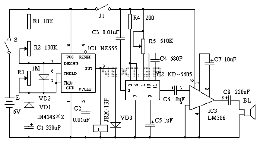
Overall, the mass air flow sensor circuit is a sophisticated assembly that integrates thermal dynamics with electronic control to optimize engine performance and efficiency, making it a vital component in modern automotive systems.This is a design circuit for mass air flow sensor circuit. The mass air flow sensors converts the amount of air drawn into the engine into a voltage signal. The primary components of the MAF sensor are thermistor, a platinum hot wire, and an electronic control circuit. The thermistor measures the temperature of the incoming air. This is the figure of the circuit; The hot wire is maintained at a constant temperature in relation to the thermistor by the electronic control circuit. An increase in air flow will cause the hot wire to lose heat faster and the electronic control circuitry will compensate by sending more current through the wire.
🔗 External reference
Related Circuits
JG series of photoelectric relay circuit. To ensure reliable operation, a Schmitt trigger circuit has been incorporated. These circuits function similarly; when light strikes the photosensitive component, its internal resistance decreases, activating the transistor VT and subsequently energizing the...
The DZ-2 was developed by RCA in Camden, NJ, for the U.S. Navy to function as a Radio Direction Finder in naval aircraft. With a contract date of June 30, 1939, the receiver exemplifies pre-war design. It operates using...
The circuits examined thus far rely on linear feedback for their operation. The magnitude of the signal returned to the negative input is always strictly proportional to the output voltage. Consequently, within the limits defined by the operational amplifier...
Cats are natural predators of rats, and the use of electronic devices to simulate meowing sounds as a repellent is an effective method. These electronic devices can produce meowing sounds at various frequencies and intervals, making them suitable for...

This inverter circuit is designed to power electric razors, stroboscopes, flash tubes, and small fluorescent lamps using a 12-volt car battery. Unlike conventional feedback oscillator inverters, this design features a separate oscillator from the output stage, allowing for easy...
This circuit utilizes a single 555 Timer IC along with a small transformer to generate high voltage for testing zener diodes with voltage ratings up to 50VDC. The 555 timer operates in astable mode, with the output from pin...