
Motor controller H-bridge using relays
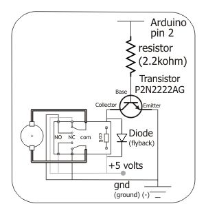
The proposed circuit employs an H-bridge configuration to facilitate bidirectional control of a DC motor. The H-bridge consists of four switches (transistors or MOSFETs) arranged in a bridge configuration, allowing for the reversal of current flow through the motor, enabling it to rotate in both clockwise and counterclockwise directions.
The integration of a DPDT relay enhances the circuit's functionality by providing an alternative method for reversing the motor direction. The relay can be operated by a microcontroller or a manual switch, enabling the user to select the desired motor operation mode. When the relay is activated, it connects the appropriate terminals of the H-bridge to the power supply, allowing for seamless control over the motor's direction.
In terms of component selection, the transistors or MOSFETs used in the H-bridge should be rated for the motor's voltage and current requirements to ensure reliable operation. Additionally, flyback diodes should be included across the switches to protect against voltage spikes generated when the motor is turned off.
The control logic for the H-bridge can be implemented using a microcontroller, which can provide PWM (Pulse Width Modulation) signals to control the speed of the motor. By varying the duty cycle of the PWM signal, the effective voltage applied to the motor can be adjusted, allowing for precise speed control.
Overall, this circuit design provides a robust solution for motor control applications, combining the versatility of an H-bridge with the reliability of a DPDT relay.To control the motor, i will be using an H-bridge with a DPDT relay like you can see on this schematic below. If you want more details, look on this.. 🔗 External reference
Related Circuits
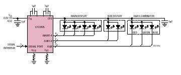
The LTC3205 is a highly integrated multidisplay LED controller. The part contains a high efficiency, low noise fractional step-up/step-down charge pump to provide power for both main and sub white LED displays plus an RGB color LED display. The...
In the circuit, when E and O are input DC voltages, the motor moves to a position corresponding to the voltage. A potentiometer, coaxially connected to the motor, is used for position feedback. When the given voltage equals the...
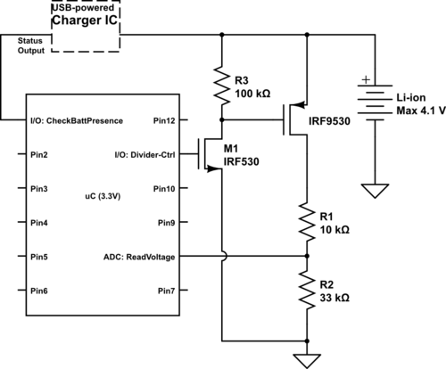
Currently using the PIC24FJ128GA010, there is a plan to utilize an Input/Output port to connect a 4.2 V LiPo battery and monitor the voltage to ensure it does not drop below 3.7 V. It is advised to avoid digital...

This LED VU Meter (volume unit) is designed to monitor and display power levels present at the speaker terminals of a stereo audio power amplifier. The levels are represented in ten discrete steps using ten LEDs for each channel,...
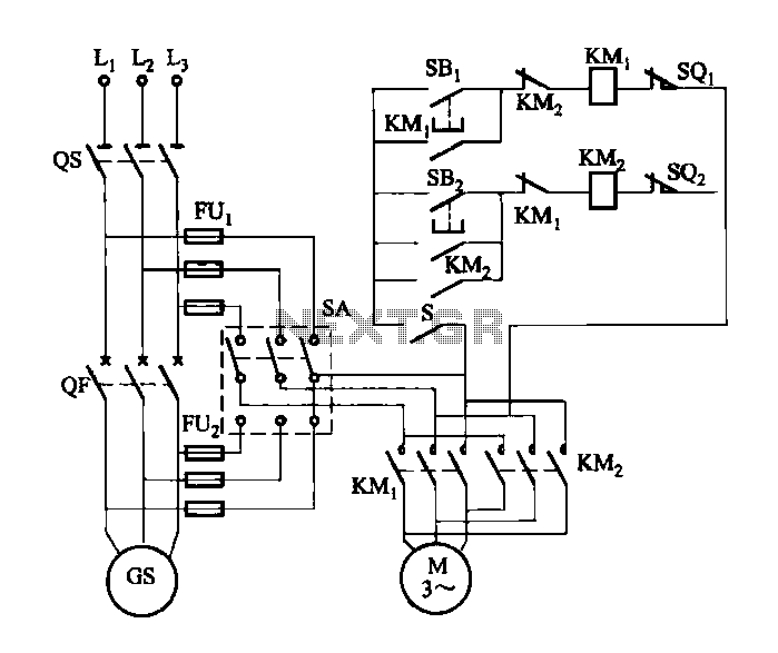
FIG M is a variable speed motor control for the opening and closing of a wicket gate. It features an electric governor. The system is activated by a power switch (SA) located on the front grid, and a toggle...

The circuit connection is illustrated in figures a and b. In figure a, a star-shaped winding is used with shunt capacitance, while figure b depicts a triangular winding with capacitance connected in parallel. The working capacitance (Cc) is calculated...