
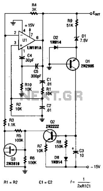
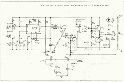
sine wave oscillator
The described circuit integrates several key components and functions, including oscillators, filters, and feedback mechanisms, to manage signal processing effectively. The operational amplifier's behavior is crucial for generating oscillations, while the interaction between the FET and gate voltage allows for precise control of current flow without the necessity for direct power input. The use of Lissajous figures aids in visualizing the waveforms, thereby enhancing understanding of the circuit's operation. The combination of low-pass and high-pass filters into a band-pass filter effectively narrows the frequency range of interest, ensuring that only desired signals are processed. Overall, this circuit exemplifies the principles of analog signal processing, demonstrating the interplay between frequency, phase, and feedback in achieving stable oscillations and controlled signal output.In case of Japan, the electricity to be using in the home is 50 Hz or 60 Hz. In case of 50 Hz, the 1-cycle sine wave occurs the 50 times for the 1 second. 60 Hz are the 60 times. There is a way of making make the Lissajous as the way of understanding that the sine wave relates to the circle. In case of the sine wave which doesn`t have the distorti on, the Lissajous becomes the true circle. The amplifier becomes the saturation state when the signal which returns to the amplifier through the feedback circuit is too big and the beautiful signal doesn`t come out. The phase means the position of the signal. At the electronic circuits, phase of the input and the output depends on capacitors, the coils, the amplifier itself.
Because it is, it doesn`t oscillate when not adjusting the phase of the input signal. The part which is composed of C1, C2, R1, R2 becomes the positive feedback circuit of the operational amplifier. With it, the operational amplifier works in the oscillation. Also, the circuit sets the oscillation frequency in the damping time constant of the CR. This oscillator begins the oscillation when it makes the mu factor equal to or more than 3. At less than 3, it doesn`t oscillate. The beautiful signal doesn`t come out by output`s being saturated when the mu factor is more than 3. The low pass filter make pass the low frequency signal and blocks the high frequency signal. The signal flows through the grounding with C1 and the output voltage becomes low when the frequency becomes high.
Oppositely, the high pass filter make pass the high frequency signal and blocks the low frequency signal. It is because the signal which passes C2 becomes little when the frequency becomes low. When combining these two, the signal in the area that the characteristic is the overlapping frequency gets to pass.
Such a filter is called the band pass filter. The circuit to be using this time changes the resistance value of the Field Effect-type Transistor(FET) at the d. c. voltage which rectified the oscillation output in the full wave. The electric current of the controlled circuit flows from the drain terminal of the semiconductor on the N-channel to the source terminal.
The semiconductor on the P channel is used for the gate. When the negative voltage is gained by the gate terminal, the electron on the N-channel(it has the negative electric charge) repels and can make the depletion region to be the junction part with the P channel. Because the electron doesn`t exist in the depletion region, the electric current doesn`t flow. When the voltage which is gained by the gate isn`t high, the depletion region is small and the flow of the drain electric current isn`t too much influenced.
It is possible to control only at the voltage of the gate. The electric power(current X voltage) isn`t necessary in spite of the control. This operation resembles the operation of the tube well. When the output voltage of the oscillator is the positive voltage, the signal spreads through the negative input terminal of IC(2/2) through D2. At the positive input terminal, it is prevented by D3 and the signal doesn`t spread. Next, when the output voltage of the oscillator is the negative voltage, the signal spreads through the positive input terminal of IC(2/2) through D3.
At the negative input terminal, it is prevented by D2 and the signal doesn`t spread. The negative voltage which is gained by the gate of TR1 becomes high when the output signal of IC(1/2) becomes big. Then, the resistance value between the drain and the source of TR1, too, becomes high. The mu factor of IC(1/2) falls when the resistance value of R3 and TR1 which is stored in series becomes high.
The output of IC(1/2) is restrained by it. 🔗 External reference
Related Circuits
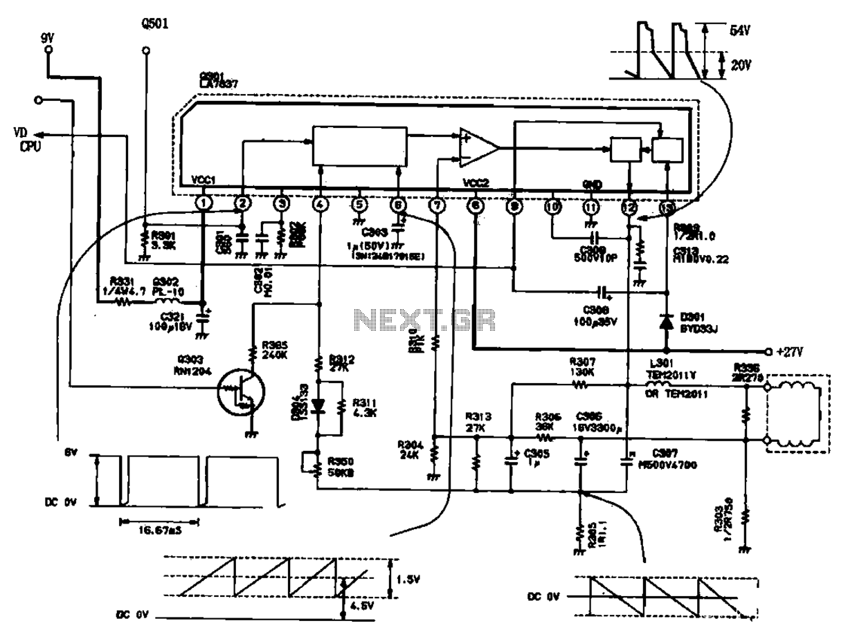
The field scanning circuit generates sawtooth waveforms essential for color television field scanning. The circuit, as illustrated in Figure 1, is utilized in the Toshiba 2150 TV. The vertical scan pulse signal is produced from the LA7837 integrated circuit,...
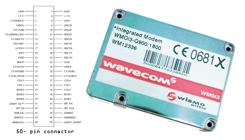
Modems are devices that connect remote devices to a computer or enable communication between multiple computers. While traditional modems typically use wired connections, the GSM modem described here operates wirelessly. It can link two computers, connect a computer to...
For variable-frequency operation, Rl and R2 can be replaced by a dual potentiometer. In electronic circuits that require variable-frequency operation, the use of a dual potentiometer as a replacement for resistors Rl and R2 can provide enhanced functionality and flexibility....
This circuit was designed to drive an impact counter, utilizing the ICL8038 as its core component. It is intended for a motor that operates a conveyor, with the motor featuring a feedback system known as a tachogenerator. Only a...
The crystal frequency stabilization of a frequency modulation circuit is illustrated below. The frequency modulation (FM) circuit utilizes crystal frequency stabilization to ensure precise frequency control and stability. This process involves the use of a quartz crystal oscillator, which...
This generator circuit utilizes an overdriven amplifier to generate a 60 Hz square wave from the 60 Hz AC line. The circuit is suitable for line-operated applications as a clock source. The generator circuit operates by leveraging an overdriven amplifier...