
Clap Sensitive On-Off Relay
This circuit utilizes a microphone as a sound sensor to detect the sound of a hand clap. The microphone converts the sound waves into an electrical signal, which is then processed by a signal conditioning circuit. This circuit typically includes an amplifier to boost the microphone's output and a comparator to differentiate between the noise level and the clap sound.
The output from the comparator triggers a flip-flop or a microcontroller, which toggles the state of the relay. The relay acts as a switch to control a larger load, allowing for various applications such as lighting or other electronic devices. When the first clap is detected, the relay is activated, and when another clap is detected, the relay is deactivated, creating a simple on/off control mechanism.
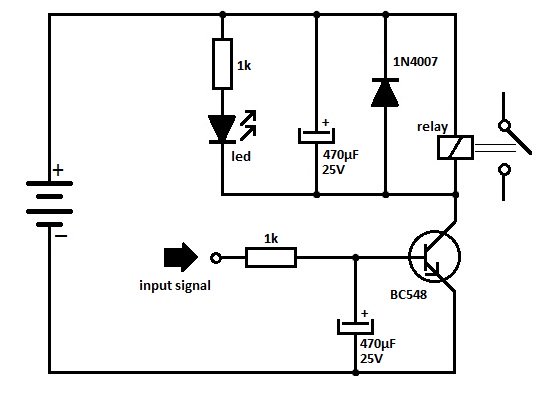
Powering the circuit with a 3V battery ensures portability and ease of use. Components such as resistors, capacitors, and possibly a diode for flyback protection may be included in the design to ensure stable operation and protect the circuit from voltage spikes generated by the relay.
Overall, this hand clap relay circuit is an efficient solution for applications requiring remote control without physical switches, providing an innovative and user-friendly interface for electronic device management.3V Battery operated, Small portable unit This circuit was intended to activate a relay by means of a hand clap. Further claps will turn-off the relay. An.. 🔗 External reference
Related Circuits
A time delay relay is a relay that remains activated for a specific duration after being triggered. This type of relay consists of a straightforward adjustable timer circuit that regulates the operation of the relay. The timing can be...

To initiate the timing process, there are two options available: either connect the START point to ground (GND), in which case the timer activates when connected to the voltage supply, or employ a switch to start the timer. The timing...
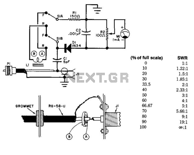
This circuit utilizes a toroidal pickup coil encircling the center conductor of a coaxial cable to measure the SWR (Standing Wave Ratio) of an antenna. The inductor (LI) consists of two turns of #26 enameled wire wound on a...
One of the serious problems in relay-operated circuits is the relay clicking or chattering during the on/off operation of the relay driver transistor. This issue can lead to unreliable circuit performance and may cause premature wear of the relay...
Circuit to close a relay when any phone extension is off-hook. Voltage at the gate of the MOSFET should be negative (1-3 volts) with respect to the source when phones are on-hook. Voltage at the gate should be positive...
This simple circuit can detect the invisible fields of voltage which surround all electrified objects. It acts as an electronic "electroscope." Regular foil-leaf electroscopes deal with electrostatic potentials in the range of many hundreds or thousands of volts. The...
Warning: include(partials/cookie-banner.php): Failed to open stream: Permission denied in /var/www/html/nextgr/view-circuit.php on line 713
Warning: include(): Failed opening 'partials/cookie-banner.php' for inclusion (include_path='.:/usr/share/php') in /var/www/html/nextgr/view-circuit.php on line 713