
Clap Triggered Switch

The Clap Triggered Switch circuit is designed to respond to sound stimuli, specifically the sound of a clap or similar sharp noise. The core component of this circuit is a microphone, which acts as a sound sensor. Upon detecting the sound, the microphone converts the acoustic energy into an electrical signal.
The circuit typically includes an operational amplifier (op-amp) configured as a comparator to amplify the signal from the microphone. The output of the op-amp is connected to a trigger mechanism, which can be a flip-flop or a microcontroller, depending on the complexity desired. The use of resistors, such as the mentioned 33kΩ and 5.6kΩ, is crucial for setting the gain of the op-amp and establishing the time constants for charging and discharging the capacitors in the circuit.
When the sound is detected, the output of the op-amp changes state, which in turn toggles the flip-flop or microcontroller. This action can drive a transistor or relay, allowing for the control of higher power devices, such as LEDs or other loads. The LEDs will toggle their state, turning on if they were previously off and vice versa.
To ensure reliable operation, the circuit may include additional components such as capacitors for noise filtering and diodes for protection against voltage spikes. The design may also incorporate a potentiometer to adjust the sensitivity of the microphone, allowing the user to fine-tune the response to different sound levels.
Overall, the Clap Triggered Switch circuit is a practical application of sound detection technology, suitable for various uses, including lighting control and interactive installations.This is circuit of Clap Triggered Switch. When the circuit detects tap, or short whistle or a clap, this circuit will toggle the LEDs. 33k and 5K6 charge The. 🔗 External reference
Related Circuits
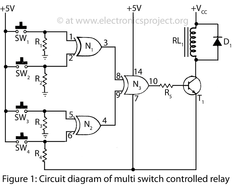
A Multi Switch Controlled Relay circuit is utilized to manage home appliances, featuring a circuit diagram that outlines the application of a multi switch-controlled relay using a single integrated circuit (IC) for various control functions. The Multi Switch Controlled Relay...
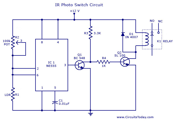
A simple photo switch circuit using the NE555 IC with a diagram and schematic. This photo switch activates a relay when light intensity exceeds a certain threshold. It serves as a light sensor circuit suitable for both home and...
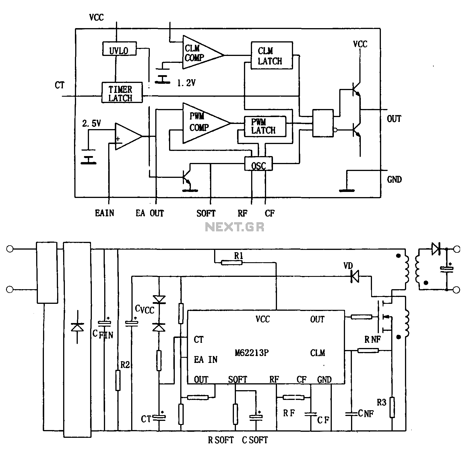
Figure (a) illustrates a block diagram of the internal architecture of the M62213FP, which is a high-speed switching power supply controller. This device includes an oscillator, PWM comparator, error amplifier, output circuit, over-voltage protection, timing latch circuit, over-current protection...
The 555 timer can be utilized to reduce the cost of incorporating a triggered sweep into an economical oscilloscope. The timer is activated by the input operational amplifier of the circuit. The application of the 555 timer in an oscilloscope...

This design utilizes standard metal gate CMOS logic rather than the typical PIC or custom chip. A 22µF capacitor charges during one half of the AC cycle and provides trigger current to the triac during both halves. The circuit employs...
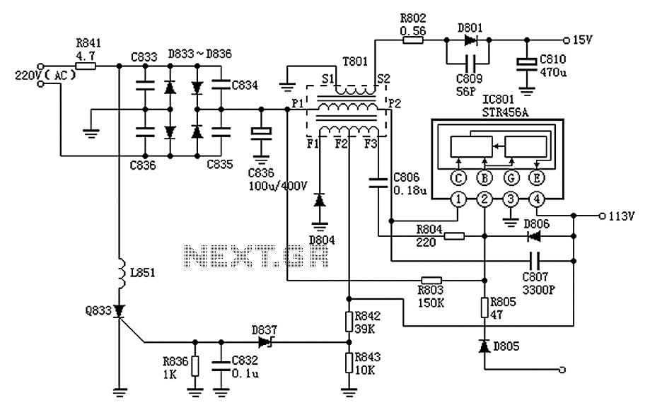
The Panasonic M12H switching power supply circuit is utilized in Panasonic models such as TC-230H, TC-2030DHN, TC-830D, and TC-840D. The circuit operates with an oscillation frequency that generates approximately 300V DC voltage at C836. The T801 transformer is involved...