
clock circuit
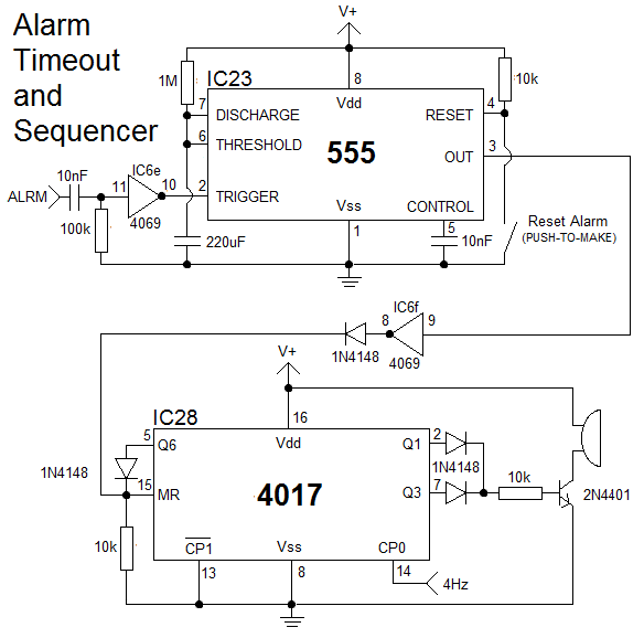
The clock's setting mechanism differs from typical digital designs that use buttons to increment digits or switches to increase speed. Instead, it incorporates a method rarely seen outside microcontroller applications. It features three setting buttons: the Mode Select button for choosing between hours, minutes, or seconds; a button to increment the selected digit; and a button to reset it to zero. Additionally, there is a button for toggling the alarm and another for resetting it. Four of these buttons (excluding the Alarm Reset button) require debouncing. Initial attempts using simple RC circuits proved unreliable, leading to the decision to implement monostable circuits instead. Each monostable has a time constant of approximately 250 ms, though this value is not critical and may depend on the specific buttons used. The clock operates effectively with various buttons, but a quicker response may be achieved by shortening the time period. An initial choice of 100 ms resulted in double triggering with lower-quality buttons.
The clock operates in four modes: Set Hours, Set Minutes, Set Seconds, and Run. The Mode Select button cycles through these modes by pulsing the clock input of a 4017 IC. A 10 nF capacitor and 10 kΩ resistor provide a brief pulse to the reset pin of the 4017 at power-on, ensuring the clock begins in Set Hours mode. This reset pulse also reaches other components requiring a reset via the power-on reset (POR) line. The four outputs (HSET, MSET, SSET, and RUN) are high when their respective modes are active and low otherwise. The 4017 resets to Set Hours mode after every fourth press of the Mode Select button. The RUN output is combined with the 1 Hz signal from the timebase and directed to the FLASH output, which causes the unselected digits to flash during setting modes or remain lit when the clock is running. The seconds and minutes displays are driven by two identical counter circuits, designed to count to 59 before resetting to 00. The first 4026 IC manages the units and generates a pulse for further operation.
This comprehensive clock design effectively utilizes a combination of ICs and discrete components, providing an innovative approach to timekeeping while maintaining user-friendly functionality through its unique setting mechanism and alarm features.The clock, which is made from 25 CD4000 ICs, three 555/556 ICs and a handful of discrete components, includes an alarm and a way of setting the clock that until now I have only seen implemented using microcontrollers. All this makes for a rather involved circuit, but I have split the schematic into a number of pages, which will hopefully make it easier to follow
The timebase is similar to many other clock designs published on line, but that`s because this is by far the best way to do it. A standard 32. 768KHz watch crystal is connected to the internal oscillator of a 4060, the output of which is divided down to 2Hz by the 4060`s 14 binary divider stages.
A final divider stage, made from one half of a 4013, gives a 1Hz signal which is used to run the clock. The timebase has two 1Hz outputs, one of which is always on and the other of which is gated by the RUN signal.
This output is only enabled when the clock is running, stopping the clock whenever it is being set. The ungated output is used to make the display flash when the clock is not running. The two diodes and resistor to the right of the schematic form an AND gate, which is used to gate the 1Hz signal. Most of the AND gates and all of the OR gates in this clock are built out of discrete components, rather than ICs.
Not only does this save board space, something which I would have run out of if even one more IC was needed, it also allows the gates to be put exactly where they are needed, saving wiring. At this point I should probably explain how you set the clock. Many digital clock designs on the internet simply have buttons to increase each digit, or a switch which makes the clock run faster.
Instead, I chose to use a method that I have only ever seen implemented with a microcontroller. The clock has three setting buttons, the first of which (the Mode Select button) allows the user to select one of the three digits (hours, minutes or seconds, if any) to change. The second button increases the current digit by one, and the third button resets it to zero. There is also a fourth button, which turns the alarm on and off, and a fifth to reset the alarm. Four of these five buttons (all of them except the Alarm Reset button) need to be debounced. At first I tried using simple RC circuits to do this, but they were unreliable. Instead I decided to use monostables. Each monostable has a time constant of approximately 250mS, but this is not critical and the value needed will depend on the buttons you use.
The circuit should work as shown with almost any button, but you may find the response to be a bit sluggish, in which case you might want to decrease the time period. I originally chose 100mS time periods, but this caused double triggering with the cheap buttons I used.
The clock has four modes: Set Hours, Set Minutes, Set Seconds and Run. Pressing the Mode Select button cycles through each of these modes by strobing the 4017`s clock input. The 10nF capacitor and 10k resistor apply a short pulse to the 4017`s reset pin at power on, ensuring that the clock always starts in Set Hours mode.
This reset pulse is also fed to other parts of the clock that need to be reset at power on by the POR (power-on reset) line. The four outputs (HSET, MSET, SSET and RUN) are high when their corresponding mode is selected and low when any other mode is selected.
The 4017 resets to Set Hours mode on every fourth press of the Mode Select button. The RUN output is OR`d with the 1Hz signal from the timebase and fed to the FLASH output. This output makes the unselected digits flash when the clock is in one of the Set modes, or light constantly when the clock is running. The seconds and minutes displays are driven by two identical counter circuits, which are wired to count to 59 before resetting back to 00.
The first 4026 drives the units, and generates a pulse 🔗 External reference
Related Circuits
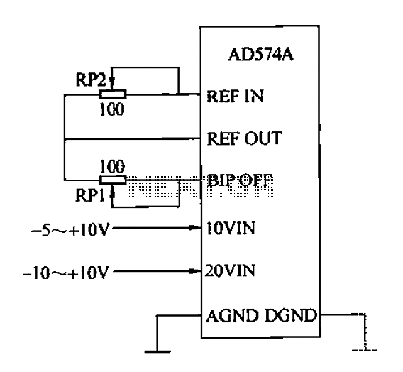
The AD574A is a high-performance 12-bit successive approximation analog-to-digital (A/D) converter that can interface directly with an 8 or 16-bit microprocessor bus. The input to the AD574A can be either unipolar or bipolar. The unipolar analog input voltage range...
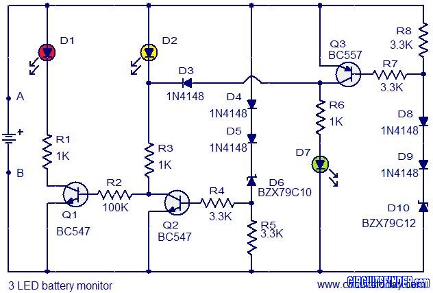
This is the circuit diagram of a 3 LED bar graph type battery monitor circuit that is ideal for monitoring the voltage level of an automobile battery. When battery voltage is 11.5V or less, transistor Q1 will be on...
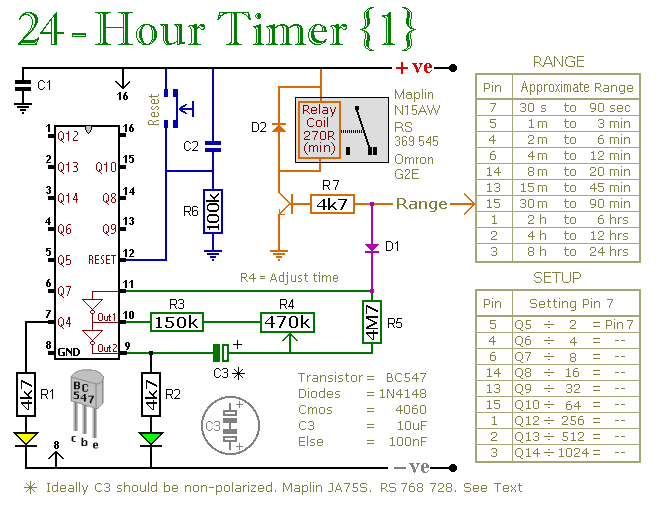
A pair of multi-range timers that provide timing periods extending up to 24 hours and beyond. Both timers are fundamentally identical, with the primary distinction being their relay behavior upon the completion of the timing cycle. Version 1 activates...
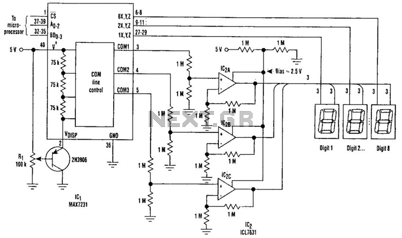
Large LCD devices with one or more displays exhibit significant driving capacitance to the driver circuits. To address this issue, the drive circuit incorporates a buffer amplifier for each of the three common lines. Each amplifier can be programmed...
The circuit is designed to operate with an audio power amplifier that uses 18V-0V-18V power rails. The specific voltage is not critical, but the feedback is referenced to an LED chain connected to a 12V rail, necessitating a separate...
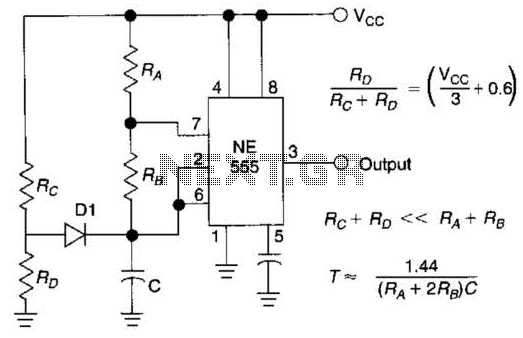
Using Rl, R7, and D1 to preset CI to one third of the supply voltage. This circuit avoids a longer first cycle period than subsequent cycles. The circuit described involves the use of resistors Rl and R7 along with diode...