
Closed loop speed control of DC motor using back emf sening
The described circuit employs a closed-loop control system for a DC motor through back EMF sensing, which is critical for maintaining optimal motor performance under varying load conditions. The integration of a PIC18F4520 microcontroller enables precise control over the motor's operation by continuously monitoring the back EMF voltage, which reflects the motor's speed. The back EMF is derived from the motor's inherent properties and is a key factor in feedback control systems.
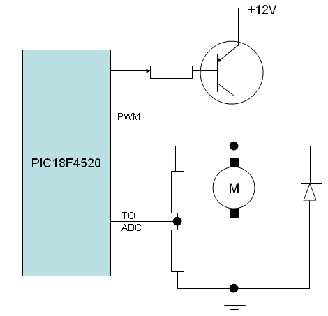
To implement this system, the PWM signal is generated by the microcontroller, determining the motor's speed through duty cycle adjustments. The back EMF is measured during a brief pause in PWM operation, allowing the motor to coast and generate a measurable voltage. This voltage is then conditioned using a potential divider to ensure it falls within the ADC's input range. The ADC converts the analog back EMF signal into a digital value, which the microcontroller processes to calculate the current speed of the motor.
For effective operation, the circuit includes a freewheeling diode that allows current to circulate when the PWM signal is turned off, preventing voltage spikes that could damage the circuitry. Additionally, the system can be enhanced by incorporating filtering components to stabilize the back EMF signal and improve measurement accuracy.
In applications where bidirectional motor control is necessary, the design complexity increases, as the back EMF must be measured differentially to account for the direction of rotation. This requires additional circuitry to switch between measurement modes based on the motor's operational state. Overall, the closed-loop control system utilizing back EMF sensing provides a robust solution for maintaining consistent motor speed in various load conditions, making it particularly suitable for robotics and automation applications.A speed closed loop control of DC motor using back emf sensing. Running a DC motor in one direction, just replace the LED with DC motor and remove the current limit resistor. Please note that motordirection reversal is not possible with this configuration. The motor speed can be varied by varying the duty cycle of PWM. But a common problem with this schematic for DC motor control is that if the motor is loaded (mechanical load), the motor speed reduces. In other words, the system is running in open loop. If we have to make a system as closed loop, we should have a mechanism to feedback the motor speed back into the controller (PIC18F4520).
Only then, the controller will know the present speed of motor and vary the duty cycle of PWM to compensate for any change in mechanical load. A DC motor when driven by external means, will generate a voltage. This voltage is also generated by the motor, when it is supplied by a DC source. This voltage is proportional to the speed of motor and is called the back emf. Best part is that the back emf is linearly proportional to the speed. To measure the back emf of motor, we stop the PWM driver for a brief period. During this brief period, the motor coasts for sometime when the current flows through the freewheeling diode.
Once the energy stored in motor inductance is exhausted, the back emf build up. This back emf is scaled to suitable voltage using the potential divider. The back emf signal is then fed into the ADC input of controller. 4. Small motors with gear used for hobby robotics usually run at high speed (gear runs at low speed, gear reduction). Such motor can easily use this scheme. 3. If the motor is configured to run on both direction (using H bridge), then the back emf measurement circuit becomes complicated (differential measurement).
🔗 External reference
Related Circuits
The core multi-resonant circuit 40 L06 has a collapse time of 1C. An auxiliary electric signal operates below its low threshold, opening Icl. The output is provided through two terminals for business use. The circuit includes components such as...
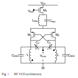
The oscillator is designed to tune from 1.8 GHz to 2 GHz for typical cellular telephony applications. An extended tuning range can be obtained by adjusting the ratio between the varactor capacitance and fixed capacitance in the tank. PMOSFETs...
There is one slight drawback to our flashing LED program. Each instruction takes one clock cycle to complete. If we are using a 4MHz crystal, then each instruction will take 1/4MHz, or 1µs to complete. As we are using...
This AC drill speed controller circuit schematic allows for the control of the drilling speed of a borer or drilling machine. This project is based on the principle that... The AC drill speed controller circuit is designed to modulate the...
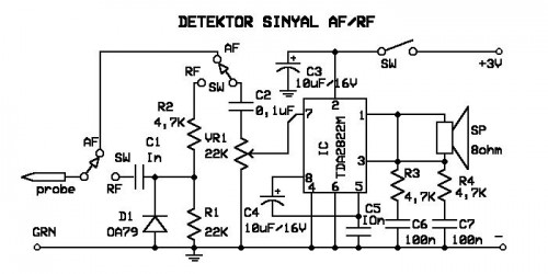
A signal detector circuit designed for detecting signals in both audio frequency (AF) and radio frequency (RF) ranges. This series is compact and straightforward to construct. The signal detector circuit operates by utilizing a combination of components such as diodes,...
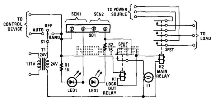
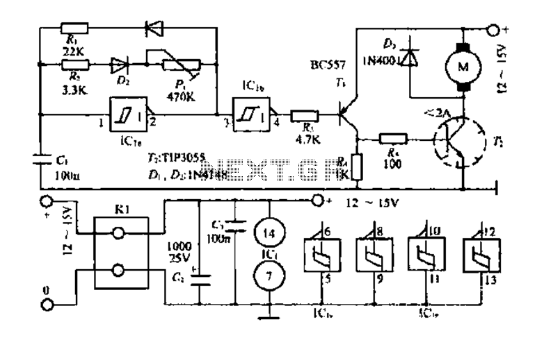
Relay K1 features a low-impedance coil, while Relay K2 is equipped with a high-impedance coil. When a sensor opens, current flows through the coil of K1, activating it. This action opens the contacts of K1, thereby preventing the reclosure...
Warning: include(partials/cookie-banner.php): Failed to open stream: Permission denied in /var/www/html/nextgr/view-circuit.php on line 713
Warning: include(): Failed opening 'partials/cookie-banner.php' for inclusion (include_path='.:/usr/share/php') in /var/www/html/nextgr/view-circuit.php on line 713