
Spike Detector For Oscilloscopes
The MAX903 comparator is a key component in high-speed pulse detection applications, particularly in scenarios where precision and rapid response are essential. Its architecture allows for the rapid processing of input signals, making it suitable for detecting short-duration pulses that other devices, such as standard TTL flip-flops, cannot handle effectively. The implementation of internal memory in the MAX903 facilitates the storage of signal levels, allowing for flexible output management and pulse stretching.
The circuit's design emphasizes the importance of power supply integrity and signal integrity, necessitating careful attention to layout and component placement. The use of decoupling capacitors close to the IC is critical to minimize noise and ensure stable operation, particularly in high-frequency applications. Furthermore, the choice of using coaxial or twisted-pair cables for signal transmission is crucial for maintaining signal fidelity and reducing electromagnetic interference (EMI).
The latch function provides a unique capability to capture and hold transient signals, making this circuit particularly useful in applications such as laser pulse detection, high-speed data acquisition systems, and other scenarios where fast signal processing is required. The adjustable hold time feature allows for customization based on specific application requirements, enhancing the circuit's versatility.
In summary, this circuit demonstrates a sophisticated approach to pulse detection, leveraging the MAX903 comparator's capabilities to address challenges associated with high-speed signal processing and noise immunity. The careful design considerations outlined ensure optimal performance and reliability in demanding electronic applications.Dynamic‚ip-‚ops ignore pulses at their inputs that are shorter than 40 ns or do not have TTL levels. This means that TTL flip-flops are poorly suited to capturing noise pulses having unknown durations and magnitudes. Anyone who has ever tried to observe very short laser pulses (15 25 ns) is familiar with this problem.
By contrast, this circ uit can detect impulses with widths less than 8 ns and amplitudes between +100 mV and +5 V. The heart of this circuit is formed by a MAX903, a very fast comparator with internal memory. The IC has separate supply pins for its analogue and digital portions. The analogue portion is powered by a symmetrical ±5-V supply. This allows the detector to also handle input voltages that are negative relative to ground. The internal memory and output stage operate from a single-ended +5-V supply, so the output signal has proper TTL levels. The MAX903 (IC1) has a special internal memory circuit (latch). The latch either connects the output of the internal comparator directly to the signal output or stores the most recent TTL level and blocks the output of the internal comparator, causing the most recent TTL level appears at the output.
This allows short input pulses to be stretched to any desired length. Despite its extremely short switching times, the MAX903 consumes only a modest 18 mW. In the quiescent state, the voltage on the Latch input (pin 5) is at 1. 75 V. This reference voltage is provided by LED D1, which draws its current via R2. In this state the latch is transparent, and a positive edge at the input appears will appear as a negative transition on the output after a propagation delay of 8 ns (tPD). This only happens if the peak voltage on the input is more positive than ground potential. C1 passes this change in the output voltage level to the Latch input (pin 5). As soon as the voltage on the Latch input drops below 1. 4 V, the internal latch switches to the Hold state. In this state, the output is no longer connected to the comparator, and the output remains low for the duration of the latch hold time, regardless of what happens with the input signal.
The latch hold time is determined by the time constant of the C3/R1 network; it has an adjustment range of 100 500 ns. Pulses of this length can be readily observed using practically any oscilloscope. This latch function in this circuit is only triggered if the input signal has a rising edge that crosses the zero-voltage level.
The internal latch remains transparent for signals in the range of 5 V to 0 V, so such pulses will not be stretched. If only positive input voltages are anticipated, the negative supply voltage is not necessary and the circuit can be powered from a single +5-V supply.
A fast circuit such as this requires a carefully designed circuit board layout. All connections to the IC must be kept very short. Decoupling capacitors C1 and C2 should preferably be placed immediately adjacent to the supply pins. Pin 3 of the IC can be bent upward and soldered directly to a length of coax or twisted-pair cable (air is still the best insulator). If a coax cable is used, the unbraided screen must not be formed into a long pigtail. It`s better to peel back a short length of the screen, wrap a length of bare wire around it and solder it directly to the ground plane.
The supply traces for the analogue and digital portions must be well separated from each other, and each supply must be well decoupled, even if only a single supply voltage (+5 V) is used. The preferred solution is to use two independent voltage regulators. 🔗 External reference
Related Circuits
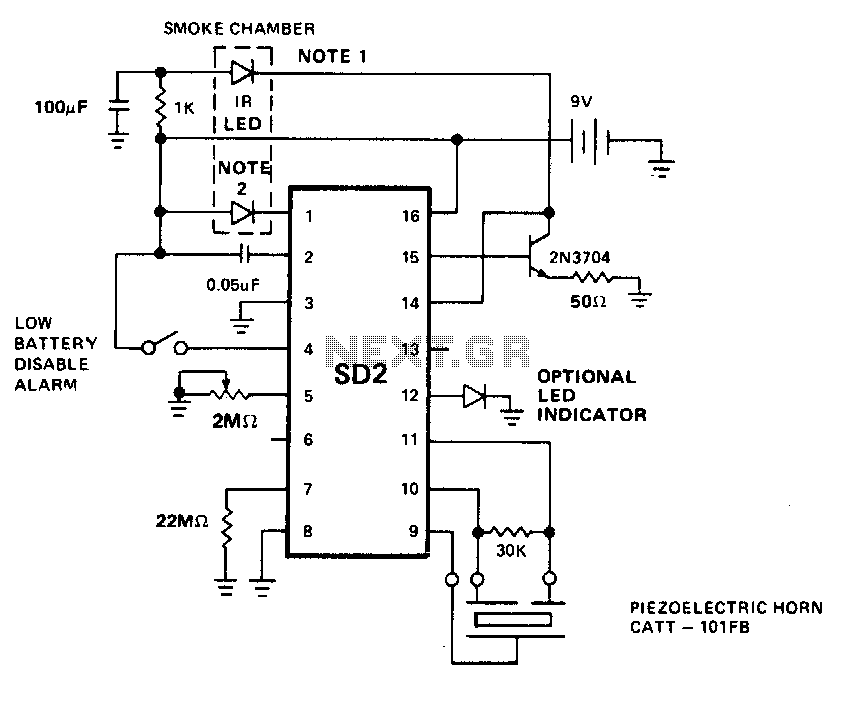
The LED predriver output pulses an external transistor, which subsequently activates the infrared light-emitting diode (IR LED) at a very low duty cycle. The desired pulse period of the IR LED is determined by the value of an external...
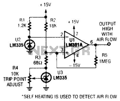
Two precision temperature sensors are utilized to measure a slight temperature difference. When airflow is present, the self-heating of the LM335 is minimized, resulting in an unequal output from the two temperature sensors. This disparity is further amplified by...
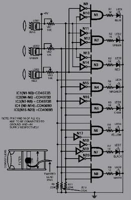
This circuit is capable of sensing eight colors: blue, green, and red (primary colors); magenta, yellow, and cyan (secondary colors); along with black and white. It is designed based on the principles of optics and digital electronics. The object...
The metal detector described in the example can detect metal objects made of highly permeable magnetic substances. The circuit operates based on several components: a power circuit, a sine wave oscillator, a PLL (phase-locked loop) circuit, and a hybrid...
This battery-powered metal detector utilizes four exclusive-OR gates from the 4030 CMOS integrated circuit. The gates are configured as twin oscillators, with a search coil acting as the inductance element in one of the oscillators. When the coil approaches...
This circuit can be constructed using readily available low-cost components, some of which may be found in a junkbox. The specified value of 22 ohms for resistor R1 results in an average current of approximately 65 mA through the...