
colours sensor detector circuit
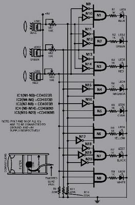
The color detection circuit utilizes a combination of photodetectors and microcontrollers to accurately identify and differentiate between various colors. The primary colors are detected using RGB (Red, Green, Blue) sensors, which measure the intensity of light in each of these three wavelengths. The readings from these sensors are then processed to determine the presence of primary and secondary colors based on predefined thresholds.
For detecting black and white, the circuit employs a light intensity measurement that assesses the overall brightness of the object. When the intensity is low, the object is classified as black, while a high intensity indicates the presence of white. The circuit's design incorporates analog-to-digital converters (ADCs) to convert the analog signals from the sensors into digital data that can be processed by the microcontroller.
The microcontroller is programmed with an algorithm that compares the sensor readings against a color lookup table, enabling real-time color recognition. This allows the system to output the detected color through a display or interface, providing immediate feedback.
In terms of hardware, the circuit may include additional components such as resistors, capacitors, and LEDs for status indication. Proper calibration of the sensors is essential to ensure accuracy and reliability in various lighting conditions. Overall, this color sensing circuit serves applications in robotics, automation, and interactive systems, where color recognition is crucial for functionality.This circuit can sense eight colours, i. e. blue, green and red (primary colours); magenta, yellow and cyan (secondary colours); and black and white. The circuit is based on the fundamentals of optics and digital electronics. The object whose colour is required to be detected should be placed in front of the system. 🔗 External reference
Related Circuits
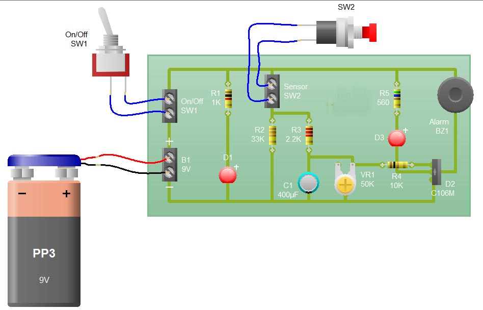
When the sensor switch SW2 is pressed, the LED D3 and the alarm are activated for a certain duration. The timing of the circuit is determined by the resistor R3 and capacitor C1. Additional details regarding the RC circuit...
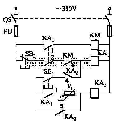
Competition among relay contacts in contactor control systems often leads to significant issues that can be cumbersome to address. In some cases, this requires the addition of numerous components. However, utilizing a negative temperature coefficient thermistor (NTC) for delay...
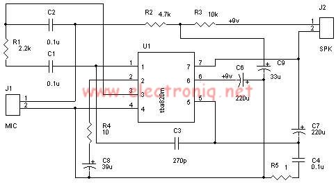
A very simple audio amplifier circuit can be designed using the TBA820M audio amplifier integrated circuit with just a few electronic components. This audio amplifier project features a high gain that allows for the detection of sounds underwater. The...

This circuit is designed as a countdown timer utilizing a countdown calculation. It employs the 555 integrated circuit (IC) as the primary control element. The 555 IC functions as a counter and a transistor switch to activate a relay...
This ultra wide range timer utilizes a 555 timer as its core component, along with two 4017 decade counters and a 4020 binary counter that function as frequency dividers, which can be selectively switched in and out. Additionally, the...
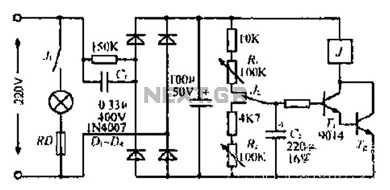
220V mains electricity is sent through a 0.33 µF capacitor (Ci) and a 50 kΩ resistive drop. A bridge rectifier composed of diodes D1 to D4 converts the AC voltage to DC. After passing through a 100 µF capacitor...