
Compact fluorescent lamp

There arise low temperature plasm. Overflowing energy mercury radiate in a UV light form. Inner side of tube is faced with luminophore, which transform UV light in to the visible light. Tube is powered by alternating current, so that function of electrodes (cathode and anode) is still changing. Because there are used switched converter, which works on tens of kilohertz, that CFL lamp doesn`t "blink" in comparison to classic strip tube lamp.
Converter, which is present in a screw cap, substitute classic ballast with a starter. Princip of function we explain on a LUXAR 11W lamp. Circuit contains supply section, which includes interference suppressor L2, fuse F1, bridge rectifier from 1N4007 diodes and filtering capacitor C4. Starting section includes D1, C2, R6 and diac. D2, D3, R1, R3 have protect function. Other parts have normal operation function. R6, C2 and DIAC mades first pulse to base of transistor Q2 and cause his opening. After start is this section blocked by diode D1. After every opening of Q2 is discharged C2. There is not possible to collect enough energy for reopening of diac. Next are transistors excitated over very small transformer TR1. It consists of ferrite ring with three windings (5 to 10 coils). Now are filaments powered over capacitor C3 from voltage rises from resonant circuit from L1, TR1, C3 and C6.
Than the tube lights up is resonation frequency specified by capacity of C3, because he has much lower capacity than C6. In this moment is voltage on a C3 over 600V in a relation to used tube. During start is peak collector current about 3 to 5 times bigger than during normal operation. When the tube is damaged, there are hazard of transistor destroying. When the gas is ionisated in a pipe, C3 will be practically shorted and thanks to this frequency goes down and changer is now drived only by C6 and changer generates much lower voltage but enough to keep the light on.
In a normal situation, when transistor opens, that current to TR1 increasing until his core is saturated and next his feedback to base drop away and transistor closes. Now opens second transistor which is excitated by reversly connected windind of TR1 and all process repeats.
Common failure is broken capacitor C3. it is possible mainly at cheap lamps, where are used cheaper components for lower voltage. Whet the pipe doesn`t lights up on time, there are risk of destroying transistors Q1 and Q2 and next resistors R1, R2, R3 and R5. When lamp starts, changer is very overloaded and transistors usually doesn`t survive longer temperature overloading.
When the pipe serve out, electronics is usually destroyed too. When the pipe is old, there can be overburned one of filaments and lamp doesn`t lights up anymore. Electronics usually survives. Sometimes can be pipe broken due to internal tension and temperature difference. Most frequently lamp fails, when power on. Repair of electronics usually means change of capacitor C3 if he is brobek. When burns fuse, probably will be damaged transistors Q1, Q2 and resistors R1, R2, R3, R5. You can replace fuse with resistor 0R5. Failures can be multiplied. For example, when is shorted capacitor there can be thermally overloaded transis 🔗 External reference
Related Circuits
Whenever there is a need for battery-powered lighting, such as for camping, solar-powered cottages, cars, boats, planes, or emergency situations, fluorescent lamps are highly appealing. They are significantly more efficient than incandescent lamps, producing much more light for less...
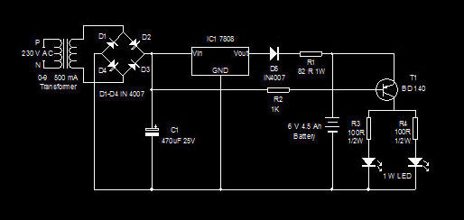
This is a high-efficiency emergency lamp that utilizes high-brightness white LEDs. It automatically activates during power failures and deactivates when power is restored. The emergency lamp circuit is designed to provide reliable illumination during power outages, utilizing high-brightness white LEDs...

The mixer is equipped with two stereo phono inputs and two stereo line-level inputs, along with a single stereo mixing channel. It includes a microphone input and a stereo main output with adjustable gain. The general circuit diagram displays...
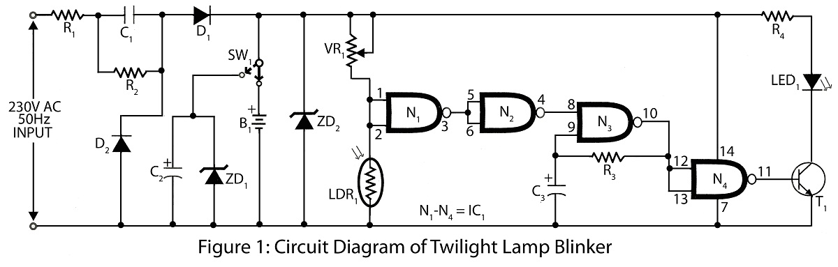
Twilight Lamp Blinker circuit can be constructed using a Light Dependent Resistor (LDR) and a single integrated circuit (IC). The circuit diagram includes a parts list for various projects utilizing the LDR and additional components. The Twilight Lamp Blinker circuit operates...
Here is a 12 volt / 2 amp lamp dimmer that can be used to dim a standard 25 watt automobile brake or backup bulb by controlling the duty cycle of an astable 555 timer oscillator. When the wiper...

Most dimmers utilize pulse width modulation (PWM) to regulate the amount of power supplied to the lamp. Those that are packaged with a switch faceplate... Dimmers that employ pulse width modulation (PWM) function by rapidly turning the power supplied to...