
Complete SS Laser Power Supply Schematics
PFN1 (manufacturer and model not specified) consists of a 36 µF, 950 V energy storage capacitor, a 0.03 mH inductor, an automatic bleeder circuit, and various connectors. The capacitor is marked with its specifications, while the inductor's value was determined through a 'ring test' using both a separate high-Q 1 µF capacitor and the one in the PFN. The original application for PFN1 was likely with the SSY1 laser head (refer to the section: A Small Nd:YAG Laser - SSY1). The maximum useful energy delivered to the flashlamp is approximately 14 to 15 J when charged to just over 900 V. Pulse Forming Network 1 illustrates the assembly with major components labeled. This unit was available from Meredith Instruments. When used without modifications, the combination of the 36 µF capacitor and 0.03 mH inductor will yield a pulse duration of 50 to 100 µs (dependent on other circuit parameters, likely closer to 100 µs in practice). This pulse duration is well matched to a Nd:YAG rod. With an appropriately designed cavity, 15 J should be sufficient to reach the threshold for a 50 mm x 4 mm Nd:YAG rod (which is presumably what it was intended to pump) and significantly more than adequate for a 25 mm rod. It is important to note that the capacitor in PFN1 is a high-quality non-electrolytic type, likely a polyester film capacitor with an Equivalent Series Resistance (ESR) of around 0.02 Ohm (in contrast to nearly 1 Ohm for a combination of electrolytic photoflash capacitors with equivalent capacitance and voltage ratings). The extremely low ESR is critical for achieving the required short pulse duration with reasonable efficiency, maximizing energy transfer to the flashlamp.
To repurpose usable components from the PFN1 casting, unsolder the capacitor wire that passes through the base and free the longer capacitor wire by detaching it from the epoxy that secures it in place. This wire can then be tucked away to prevent damage (e.g., coiling it tightly at the end of the capacitor). A hacksaw or rotary tool may be employed to cut through the thin cast metal surrounding the capacitor, taking care to only penetrate deep enough to reach the robust rubbery potting compound. This process may require multiple cuts along the length of the casing and around the base of the capacitor where other components were mounted. Careful prying of the metal pieces from the potting compound should leave the capacitor adhered to the base. It is preferable to make additional cuts rather than exert excessive force. Although the potting compound can be peeled away from the bottom of the capacitor, it may adhere more strongly than to the yellow Mylar, and leaving it in place may be advisable.This chapter contains circuit diagrams for several power supplies for pulsed solid state lasers. These include units suitable for driving the popular Hughes ruby and YAG rangefinder laser assemblies as well, one using the flash from a disposable pocket camera, and a high energy flashlamp power supply for that 8 inch long surplus NOVA laser rod you have been saving. :) The pulse forming network is what determines the performance of a pulsed solid state laser. Thus, there is a great deal of flexibility in the design of the capacitor charger and trigger circuits. Systems designed for other applications can often be adapted for solid state laser power supplies. See the chapter: SS Laser Power Supplies for more information. And the schematics in this chapter can be easily modified for larger, smaller, or different types of solid state lasers.
WARNING: All of these systems are potentially lethal - some just more lethal than others. Hey, but when you`re dead, it probably doesn`t matter how well done you are. Before even thinking about building or going near one of these systems, make sure you have thoroughly read, understand, and follow the laser and electrical safety guideline provided elsewhere in this document! PFN1 (manufacturer and model unidentified) is a combination of a 36 uF, 950 V energy storage capacitor, 0.
03 mH inductor, automatic bleeder circuit, and various connectors and other stuff. The capacitor is marked with its rating but the inductor is not and its value was determined by performing a `ring test` using both a separate high-Q 1 uF capacitor and then the one in the PFN. The original application for PFN1 was most likely to be used with the SSY1 laser head (see the section: A Small Nd:YAG Laser - SSY1 ).
The maximum useful energy into the flashlamp is around 14 to 15 J when charged to just over 900 V. Pulse Forming Network 1 shows the assembly with major components labeled. This unit is/was available from Meredith Instruments. When used without modification, the combination of the 36 uF capacitor and 0. 03 mH inductor will result in a 50 to 100 us pulse duration (dependent on other circuit parameters, probably closer to 100 us in practice). This is quite well matched to a Nd:YAG rod. With a well designed cavity, 15 J should be enough to threshold a 50 mm x 4 mm Nd:YAG rod (which is what it apparently was intended to pump) and considerably more than enough for a 25 mm rod.
Note that the capacitor in PFN1 is a very high quality non-electrolytic type. It may be a Polyester film capacitor with an ESR (Equivalent Series Resistance) of around 0. 02 Ohm (compared to almost 1 Ohm for a combination of electrolytic photoflash caps with the same uF and V ratings). The extremely low ESR is essential to achieve the required short pulse duration at reasonable efficiency (i.
e. , maximizing energy transfer to the flashlamp) or at all. Remove the other usable components from the PFN1 casting, unsolder the capacitor wire that goes through the base, and free up the other longer capacitor wire by breaking it free of the Epoxy globs fastening it in place and then tuck it out of the way so it won`t get damaged (e. g. , wrapped in a tight spiral on the end of the capacitor). Use a hack saw or rotary tool to slice the thin cast metal surrounding the capacitor just deep enough to reach the tough rubbery potting compound and no deeper.
This may have to be done in several places lengthwise, as well as around the base of the capacitor (next to where the other components were mounted). Then, carefully but persuasively pry the metal pieces from the potting compound leaving the capacitor stuck to the base.
It`s better to make some more cuts than to use a lot of force. It should be possible to peel the potting compound from the bottom of the capacitor but the adhesion there seems to be much stronger than to the yellow Mylar and it doesn`t look so bad left in place. :) This power sup 🔗 External reference
Related Circuits
The range of this FM transmitter is approximately 100 meters when powered by a 9V DC supply. The circuit consists of three main stages. The first stage is a microphone preamplifier utilizing a BC548 transistor. The second stage features...
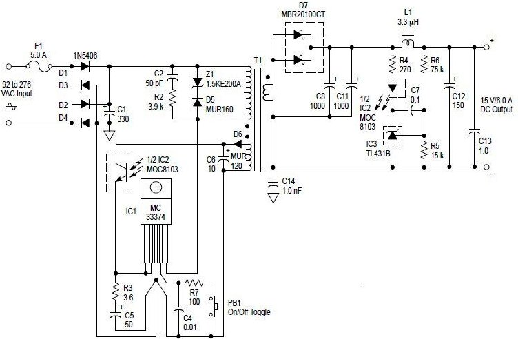
An AC to DC switching power adapter circuit with a maximum output power of 90W. The switching power supply is constructed using a high voltage power switching regulator IC, the MC33374, along with several additional components. The MC33374 IC...
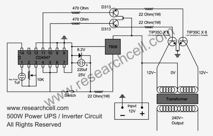
This circuit diagram features a single variable resistor utilized to adjust the frequency of a 240V AC output current. It is advisable to use a frequency meter to modify the frequency from 50Hz to 60Hz according to specific requirements....
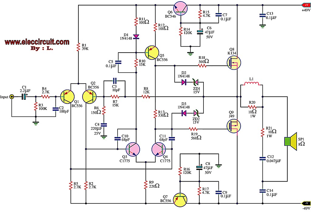
This is the first MOSFET power amplifier designed, featuring a comprehensive circuit. As a 60-watt power amplifier, it is adequate for typical usage. The 60-watt MOSFET power amplifier circuit is designed to deliver high efficiency and robust performance for audio...
The circuit comprises an N-MOSFET voltage follower (T1, common drain) and a current source (T2, NPN Darlington). The current source is set to 2.2 Amps. With a supply voltage of 40V, the circuit can deliver approximately 17W into an...
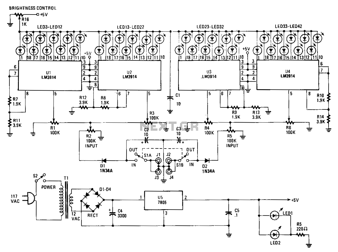
The Stereo Power Meter consists of two identical circuits and a power supply. Each circuit features two LM3914 display chips, which include 10 voltage comparators, a 10-step voltage divider, a reference voltage source, and a mode-select circuit that allows...