
Current-To-Frequency Converter
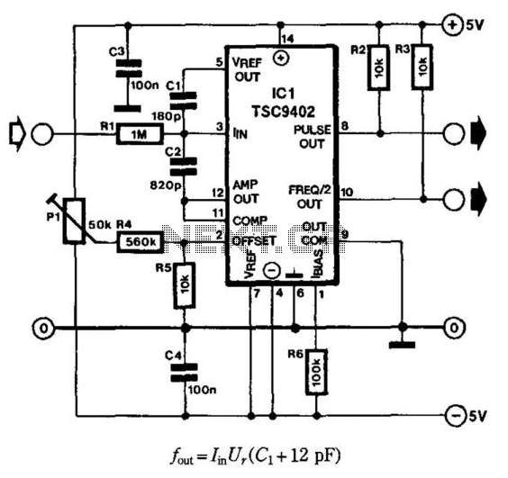
The Teledyne Semiconductor Type TSC9402 integrated circuit is designed to convert input current into a corresponding frequency output, making it an ideal choice for applications requiring precise current measurement and conversion. The circuit operates effectively within a specified input voltage range of 10 mV to 10 V, which allows for versatile integration in various electronic systems. The maximum input current of 10 mA ensures that the circuit can handle substantial current levels without compromising performance.
The output frequency generated by the TSC9402 is directly linked to the input current, with a conversion factor of 1 kHz/mA. This means that for every milliampere of input current, the output frequency increases by 1 kHz, allowing for easy scaling and interpretation of the output signal. The circuit's dual-output configuration enhances its utility: the pulse output at pin 8 provides a rapid response to changes in input current, while the square wave output at pin 10 can be used for further processing or interfacing with other circuitry.
Calibration is a critical aspect of ensuring accurate performance. The procedure outlined involves connecting a frequency meter to monitor the output at pin 8 while applying a known input voltage. This allows for precise adjustments to be made via the potentiometer P1, ensuring that the output frequency aligns with the expected values. The ability to adjust the circuit components, such as replacing R1 or shunting C1, provides flexibility in fine-tuning the circuit to achieve the desired performance, particularly if the output frequency does not meet specifications during initial testing.
Overall, the TSC9402 IC offers a robust and flexible solution for current-to-frequency conversion, with straightforward calibration procedures that facilitate its implementation in various electronic applications. Teledyne Semiconductor"s Type TSC9402 IC is eminently suitable as an inexpensive current-to-frequency conver ter. The maximum input current of the design shown in the diagram is 10 (input voltage range is 10 mV to 10 V), while the output frequency range extends from 10 Hz to 10 kHz. The conversion factor is exactly 1 kHz/. The factor can be altered by changing the value of Rl—as long as the maximum input current of 10 is not exceeded.
The circuit has two outputs. That at pin 8 is a short-duration pulse, whose rate is directly proportional to the input current; that at pin 10 is a square wave of half the frequency of the pulse at pin 8. Calibrating the circuit is fairly simple. Connect a frequency meter to pin 8 (preferably one that can read tenths of a hertz) and connect a voltage of exactly 10 mV to the input (check with an accurate milli-voltmeter).
Adjust PI to obtain an output of exactly 10 Hz. Next, connect a signal of exactly 10 V to the input and check that the output signal has a frequency of 10 kHz. If this frequency cannot be attained, shunt CI with a small trimmer or replace Rl by a resistor of 820 kfi and a preset of 250 KOhmhm.
🔗 External reference
Related Circuits
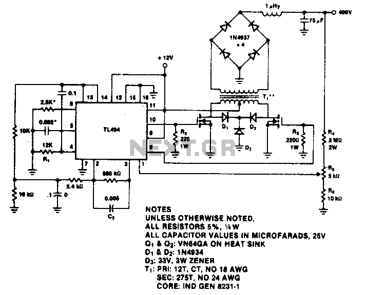
The TL494 switching regulator controls the operating frequency and regulates output voltage. The switching frequency is approximately 100 kHz for the specified values. Output regulation typically varies by 15% from no-load to full 60 W. The TL494 is a versatile...

This circuit operates effectively across a broad frequency spectrum. XTAL 1 serves as a fundamental-frequency crystal. Tl and CI are adjusted to match the input frequency. This circuit can be utilized as a straightforward shortwave converter for AM radios,...
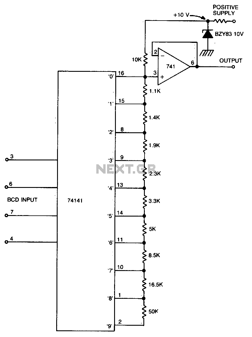
This circuit converts a four-bit Binary-Coded Decimal (BCD) into a variable output voltage ranging from 0 to 9 volts in 1-volt increments. The SN74141 functions as a Nixie tube driver, featuring ten open-collector outputs. These outputs are utilized to...
The circuit is a DC to DC converter utilizing a standard 12 VAC center-tapped power transformer configured as a blocking oscillator. Although the circuit exhibits low efficiency, it generates a high voltage suitable for low-power applications. The input battery...
First circuit is for connecting VGA card to video projector or a monitor which accept VGA card frequencies and has RGB + Composite sync input. This circuit has been successfully used with Electrohome Projection Systems ECP 4100 data and...
In certain scenarios, a 5-V supply voltage is available, but a portion of the circuit requires a lower supply voltage. The TPS62000 series voltage regulator from Texas Instruments is an appropriate solution for applications with a current consumption of...