
Crystal Sine Wave Oscillators
In electronic design, the use of quartz crystals in oscillators is pivotal for applications requiring precision timing and frequency stability. The inherent properties of quartz crystals, such as their high Q factor, enable the creation of oscillators that can maintain a consistent frequency, even in the presence of environmental changes. The integration of quartz crystals into circuits can be realized through various configurations, such as the Colpitts and Hartley oscillators, which utilize the crystal's characteristics to enhance performance.
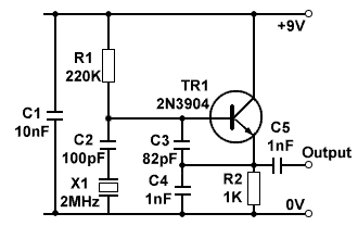
In a typical Colpitts oscillator design, the quartz crystal is connected in parallel with the tank circuit, allowing it to resonate at its fundamental frequency. The feedback loop in the oscillator circuit is crucial for sustaining oscillations, with the crystal providing the necessary frequency stabilization. The equivalent circuit of a quartz crystal reveals its behavior as a combination of inductance, capacitance, and resistance, which can be modeled effectively in simulation tools to predict performance under different conditions.
Hartley oscillators, on the other hand, employ the crystal in series mode, where it acts as a low impedance element in the feedback path. This configuration is particularly advantageous for applications requiring low phase noise and high-frequency stability. The design considerations for both types of oscillators involve careful selection of components to ensure minimal drift and optimal performance across the desired frequency range.
Overall, the implementation of quartz crystal oscillators in modern electronic circuits has revolutionized frequency generation, providing reliable and accurate timing solutions across numerous applications, from telecommunications to consumer electronics. As technology advances, the integration of these oscillators into compact, efficient designs continues to expand, facilitating the development of sophisticated electronic systems.Where good frequency stability is required, in applications such radio transmitters, basic LC oscillators cannot guarantee to hold their frequency without some drifting, which can be caused by quite small changes in supply voltage (although stabilised power supplies help avoid this) and changes in temperature. The effects of resistance and stray capacitance within the circuit can also cause the oscillator to operate at a slightly different frequency from that calculated using just the values of L and C. In most cases this can be overcome by making the tuned tank` circuit have as high a Q factor as possible.
With ordinary inductors and capacitors, Q factors more than a few hundred are not possible, but by using quartz crystals Q factors well in excess of 10, 000 can be achieved. Crystals may be used increase frequency stability in RF oscillators such as Hartley and Colpitts. The crystal may be used either in parallel mode` e. g. as an inductor operating at a frequency between ’1 and ’2 as part of the resonating tuned circuit, as shown in the crystal controlled Colpitts oscillator in Fig 2.
5. 1, or in series mode` where the crystal is acting as a highly selective low impedance at ’1 in the feedback path as shown in a Hartley oscillator in Fig. 2. 5. 2. The quartz crystal is a piezo-electric device, and will both produce a voltage across it when it is subjected to some mechanical distortion such as slight bending, or will distort slightly when a voltage is applied across it.
Therefore applying regular voltage pulses will cause the crystal to bend, and the bending will in turn create voltage pulses in phase with the applied pulses, that will reinforce them and cause oscillation. The frequency at which this reinforcing effect occurs is the resonant frequency of the crystal, and this is determined by the physical size of the crystal and by the way the crystal is cut in relation to its atomic structure.
When a quartz crystal is accurately cut and prepared, it is almost perfectly elastic. This means that once oscillations start, they take a long time to die away. Fig 2. 5. 3 shows the circuit (schematic) symbol for a quartz crystal and its equivalent circuit. Notice that in effect it contains all of the properties (L, C and R) normally associated with a tuned circuit. It can therefore be used to replace either a series tuned circuit or a parallel tuned circuit, and the graph of its impedance (Z) shows two resonant frequencies ’1 and ’2.
When used in series mode the crystal exhibits very low impedance at ’1, and in parallel mode, a very high impedance at ’2. In practice, because of the extremely narrow bandwidth caused by the crystal`s very high Q factor, these frequencies are close enough together to be considered the same for many purposes.
Crystal oscillators can produce either sine wave or square wave outputs over a very wide range of frequencies, usually from one or two MHz up to several hundred MHz. Crystals are produced to resonate at many different specific frequencies for particular applications, but the range of available frequencies is made much greater by various techniques such as frequency division, where the frequency of a crystal oscillator is sequentially divided by 2 many times by digital dividers, to a much lower frequency.
Because any slight errors are also reduced by the same division process, the final low frequency is much more accurate. Crystals can also be made to resonate at higher multiples of their basic resonant frequency. One of these higher multiples, called overtones) can then be selected using a conventional LC circuit.
By using these frequency division and overtone techniques a much wider range of crystal frequencies can be achieved. In modern circuitry it is far less common to find crystal oscillators constructed from discrete components, as many ready-made crystal oscillators are available.
Both square wave and sine wave oscillators are 🔗 External reference
Related Circuits
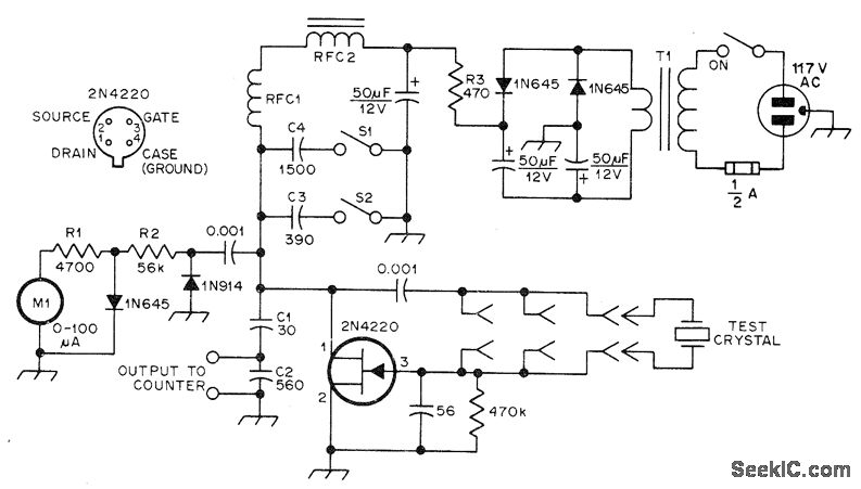
The JFET Pierce oscillator is designed to test any crystal within a frequency range of 50 kHz to 25 MHz, accommodating the upper frequency limit of fundamental-mode crystals without the need for tuning. It is capable of driving a...
Common non-sinusoidal oscillator circuit, waveform and frequency formula - sawtooth oscillator - use blocking oscillator The sawtooth oscillator is a type of non-sinusoidal oscillator that generates a waveform characterized by a linear rise in voltage followed by a rapid drop....
Oscillating circuits (coils) are constructed on a ferrite bar. For long wave reception, winding "1-2" consists of 135 turns, while winding "3-4" has 20 turns. For medium wave reception, winding "1-2" has 75 turns, and winding "3-4" has 7...
Liquid-crystal displays (LCDs) are available in various sizes and configurations, including their pinouts. Many of these displays require the manufacturer's documentation for proper usage, which is often difficult to locate when needed. Consequently, a small tester designed to identify...
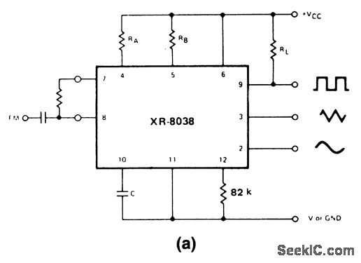
These circuits are similar to that of Fig. 5-47, except that they provide for FM or sweep modulation. Circuit 5-50A is used for FM with small deviations, approximately ±10%. Circuit 5-50B is designed for a sweep range of 1000:1....
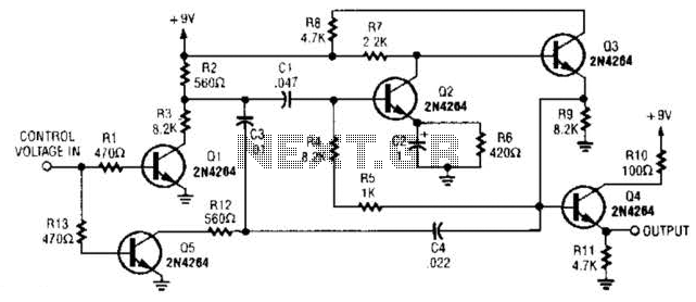
A DC control voltage varies the effective resistance in the feedback network consisting of capacitors C4, C3, C1 and resistors R12, R3. Additionally, Q2 and Q3 serve as the oscillator transistors. The circuit operates by utilizing a DC control voltage...