
Small Stepper Motor

The L293D Motor Drive Shield is designed to control DC motors and stepper motors, providing the necessary current and voltage levels for effective operation. It can drive up to two DC motors simultaneously, with each output capable of supplying up to 600mA. In this case, the motor in question draws 400mA per coil, which is within the shield's specifications, allowing for safe operation under normal conditions.
The confusion with the pinouts is a common issue when dealing with motors and motor drivers. Typically, stepper motors consist of two coils, each requiring a specific sequence of energization to achieve rotation. The L293D shield requires the correct identification of these coils to ensure proper functionality. The yellow and orange wires are likely connected to one coil, while the brown and black wires are connected to the other. It is crucial to ensure that these connections are made correctly to prevent unexpected behavior.
The observation of resistance between the orange and brown wires is concerning, as it suggests a possible short circuit or incorrect wiring. This condition can lead to excessive current draw, causing the H-bridge to overheat, which may explain the rapid temperature increase during operation. It is advisable to double-check all connections and ensure that the motor is wired in accordance with the intended configuration.
When programming the motor to perform a full rotation, the calculation for the number of pulses (48) is based on the step angle of 7.5 degrees per step. However, if the motor is only completing a quarter rotation, it may indicate an issue with the control signals or the wiring configuration. Adjustments to the pulse sequence, timing, or speed settings may be necessary to achieve the desired full rotation.
In summary, careful attention to the wiring configuration, verification of connections, and proper programming of the control signals are essential for the successful operation of the motor with the L293D Motor Drive Shield. Addressing the resistance issue and ensuring correct coil identification will help prevent overheating and achieve the intended motor performance.Trying to get this motor to work with a L293D Motor Drive Shield the shield is capable of handling 600mA per coil, this motor according to the data here takes 400mA (presumable per coil) so should be good there. However the data sheet here does not relay explain the pin outs only coil A and coil B but not which wires are which coil, the truth t
able is also a bit confusing, I am a programmer and i cant read it. i tried to do my own truth table and it seems to confirm my guess that yellow and orange is one coil, and brown and black is another coil, . however I am also showing connectivity/resistance between orange and brown, . that should not happen correct when i hook it up in what should be (as far as i can tell) the correct pin out, (Yellow/Orange as coil B) and (Brown/Black as coil A).
and setting full rotation to 48 (360/7. 5=48) then tell the motor to do one full rotation (48 pulses) (speed 10). All i get is a quarter rotation and a Hbridge chip that`s getting way to hot very quickly, 🔗 External reference
Related Circuits
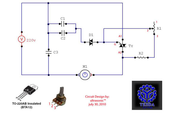
This circuit functions as a motor controller, allowing for easy control and variation of the RPM and phase of an AC motor. The power source is directly 220VAC, and it can handle a load of approximately 1 horsepower AC...
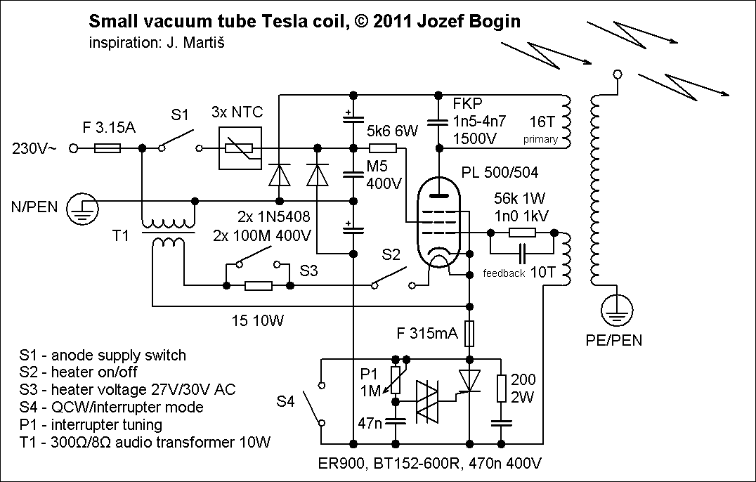
To complement flyback drivers, X-rays, and other high-voltage applications, a decision has been made to construct a Tesla coil. Due to residing in a flat, there is limited space for accommodating and operating large coil designs, not to mention...
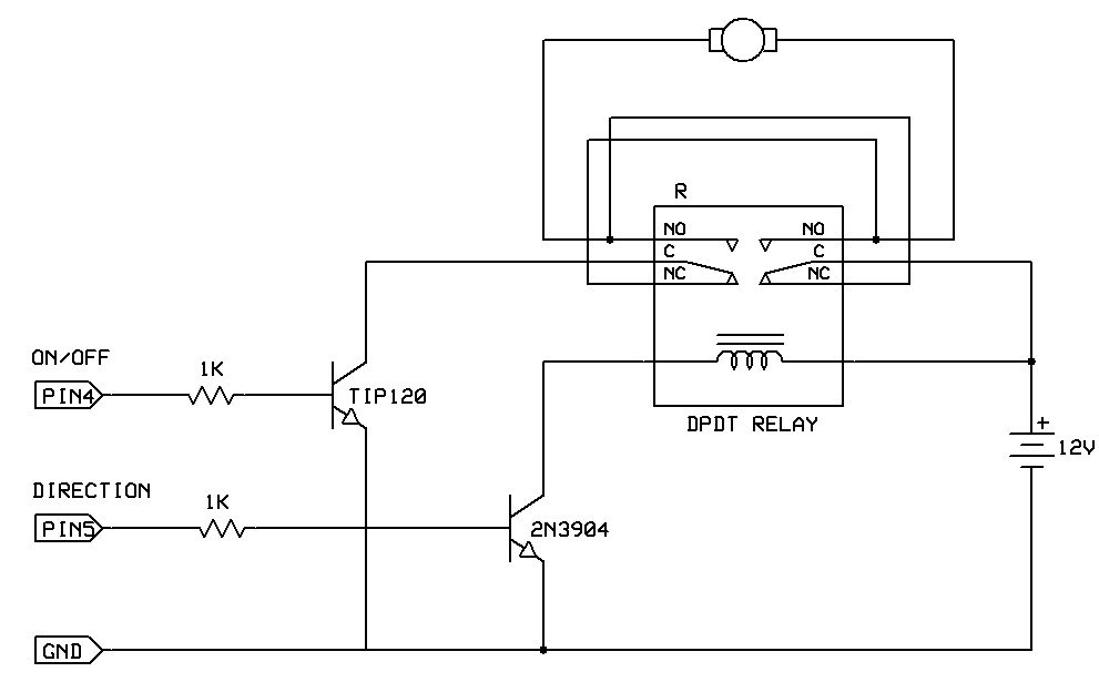
One of the simplest methods to enable a motor to rotate in both directions is by utilizing a double-pole, double-throw (DPDT) relay. This setup requires two transistors and two Stamp pins: one for on/off control and the other for...
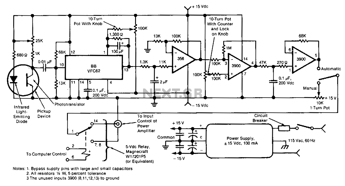
This electronic motor-speed control circuit is designed to operate in an electrically noisy environment. The circuit includes an optoelectronic pickup device, which is placed inside the motor housing to provide a speed feedback signal. The circuit automatically maintains the...
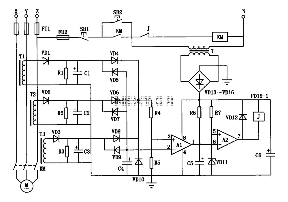
A current three-phase motor phase protection circuit is designed to detect three-phase current using homemade small current transformers T1, T2, and T3. The current signals are collected by rectifiers VD1, VD2, and VD3, while capacitors C1, C2, and C3...
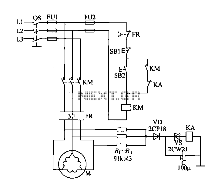
Delta connection motor phase failure protection circuit is illustrated in the figure. Its protective function involves three resistors, R1, R2, and R3, which are connected to form an artificial neutral point. When a motor phase failure occurs, an offset...