
cv mega mixer
The module's design emphasizes versatility in mixing both audio signals and control voltages, making it suitable for various applications in synthesizer setups. The dual operational amplifier configuration allows for efficient signal processing, enabling complex mixing and modulation techniques. The ability to control multiple VCAs with independent outputs enhances the creative possibilities for sound design, particularly in live performance scenarios. The inclusion of offset controls permits nuanced adjustments to the output signals, allowing for dynamic soundscapes and spatial effects. Furthermore, the detailed assembly instructions highlight the importance of careful construction and testing, ensuring reliability and performance in the final product. The design accommodates expansion for users who may wish to integrate additional inputs, reflecting the modular nature of contemporary electronic music production. Overall, this enhanced DC mixer module represents a robust solution for audio and CV mixing in modern synthesizer applications.This module is an enhanced version of the D. C. mixer designed for both audio and CV mixing. It has both non-inverting (adding) and inverting (subtracting) inputs, as well as a master level control. It also features two inverting outputs, one (out2) that is offset by the master level control, and the other (out3) which has independent offset and ce
nter inputs. Feed it several control voltage sources, for example from a bank of Psycho LFOs. Use the non-inverting output to control one VCA, and the offset inverting output (out2) to drive a second VCA, giving a pseudo random panning effect, the overall output level of which can be controlled by the master level control. The core of the circuit is quite conventional, using two op-amps in a unity gain inverting configuration.
The first stage mixes the signals from the six inputs, one of which is an expansion input and requires the use of external resistors. The output signal from this op-amp is then sent to the second stage where it is mixed with six more inputs, the inverting inputs, again one of which is an expansion input and requires the use of external resistors.
The feedback resistor in this stage is variable, one half of a dual pot, allowing the output level to be controlled. The normal output (out1) is taken from the output of this op-amp via a 1k resistor. This signal is also fed to two more inverting stages. The first again an op-amp in a unity gain inverting configuration. This time, an offset voltage is mixed with the incoming signal, the offset voltage being derived from the second section of the output level pot in such a way that the offset is reduced as the output level is reduced.
When the output level is zero, the offset will also be zero. The second inverting stage has no inbuilt offset and will reflect around the 0 volt line, though has two inputs so that the reflection point can be varied, one inverting (offset), and the other non-inverting (center). Please note, an earlier version of the PCB was accidently sent to the etchers. It is functionally fine if you make a small modification. The connections on the PCB marked LC and LB should have a 47k resistor installed between them. The resistor in the feedback path of the second op-amp should be omitted, instead, this is where the pot connections for LC and LB should go.
See the second overlay above. Before you start assembly, check the board for etching faults. Look for any shorts between tracks, or open circuits due to over etching. Take this opportunity to sand the edges of the board if needed, removing any splinters or rough edges. When you are happy with the printed circuit board, construction can proceed as normal, starting with the resistors first, followed by the IC sockets if used, then moving onto the taller components.
When inserting the ICs in their sockets, take care not to accidentally bend any of the pins under the chip. Also, make sure the notch on the chip is aligned with the notch marked on the PCB overlay. If you wish to have more than five inverting or non inverting inputs, extra 47k resistors will be required, each running between the extra input jacks or level pots and the EXP (non-inverting) or IEXP (inverting) pads on the PCB.
🔗 External reference
Related Circuits
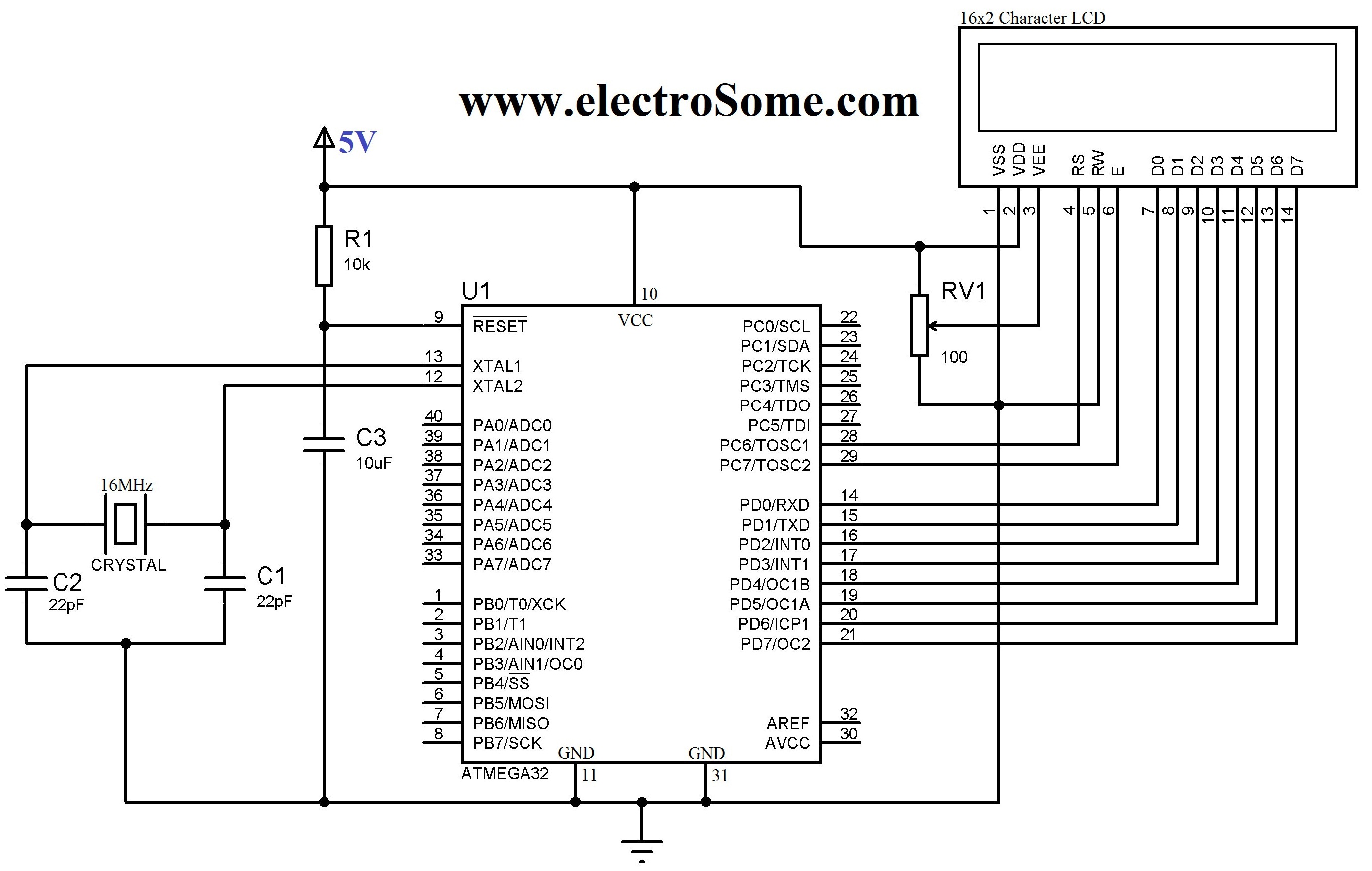
An LCD (Liquid Crystal Display) is a widely used electronic display found in devices such as calculators, laptops, tablets, and mobile phones. The 16G-2 character LCD module is a fundamental component frequently utilized by electronics enthusiasts and integrated into...
Development board featuring high-power relays, opto-coupled inputs, a power supply circuit, a crystal oscillator circuit, and an RS232 port, along with ICSP and JTAG ports. The JTAG connector utilizes a 5x2 pin configuration for in-circuit programming. This development board is designed...
The mixer consists of two transistor-based preamplifiers. The first one, designated as "Mike," provides high gain and is designed to work effectively with a standard dynamic microphone. The second preamplifier can be used to control audio input from a...
The simplest one-transistor audio mixer circuit diagram available. It utilizes a single transistor and can accommodate multiple audio signals, limited only by the user's budget. BC10. The one-transistor audio mixer circuit is a fundamental design that demonstrates the principles of...
This document outlines the procedure for creating a simple RPM meter using the AVR ATmega8 microcontroller. The RPM meter designed will operate in a contactless manner. The RPM meter circuit utilizes the AVR ATmega8 microcontroller, which is a popular 8-bit...
This project automates home appliances via a Bluetooth-enabled PC. A USB Bluetooth adapter is utilized on the PC side, while a Serial Bluetooth module is employed for communication. This project involves the integration of a Bluetooth-enabled PC with home appliances...
Warning: include(partials/cookie-banner.php): Failed to open stream: Permission denied in /var/www/html/nextgr/view-circuit.php on line 713
Warning: include(): Failed opening 'partials/cookie-banner.php' for inclusion (include_path='.:/usr/share/php') in /var/www/html/nextgr/view-circuit.php on line 713