
Dark and Light Activated Relay

The described circuit operates as a simple light detection system, utilizing a photoresistor (LDR) to sense ambient light levels. The photoresistor's resistance decreases with increasing light intensity, allowing it to function effectively as a variable resistor in the circuit.
In this configuration, the photoresistor is connected in a voltage divider arrangement with a fixed resistor. This setup produces a voltage output that varies based on the light level detected by the photoresistor. The output voltage is fed into the base of a transistor, which acts as a switch.
When the light level falls below a predetermined threshold, the voltage at the base of the transistor exceeds the base-emitter threshold voltage, turning the transistor on. This action allows current to flow from the collector to the emitter, thereby activating the relay. The relay, once energized, can control a larger load or device, such as a light or alarm system, making it suitable for applications in automatic lighting control or security systems.
The potentiometer in the circuit provides a means to fine-tune the sensitivity of the light detection. By adjusting the potentiometer, the user can set the specific light level at which the relay will activate, allowing for customization based on the environment in which the sensor is deployed.
Overall, this basic dark and light sensor circuit is an effective solution for applications requiring automatic responses to changes in ambient light conditions.This is the basic dark and light sensor which using photoresistor as sensing component. The transistor act like as a switch, when the switch in on condition then the relay will be activated. The potensiometer adjust the trigger on level. Th.. 🔗 External reference
Related Circuits
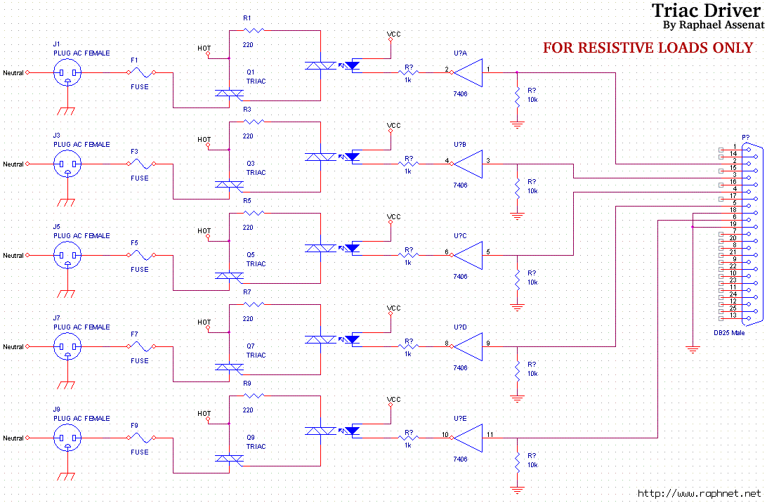
Controlling room lighting using a computer. Triacs and opto-couplers have been purchased for this purpose. A schematic was drawn and a prototype was built, which functioned correctly. Although not visible in the pictures, there is a cable extending from...

If you have ever used a 12V flasher relay system, typically a mechanical type, for general automotive applications, today we will attempt to build a 12V flasher relay circuit. The 12V flasher relay circuit is a crucial component in automotive...

This is a design circuit for a soft light dimmer. The circuit utilizes the IGBT STGP10N50A and the TS555 timer as the main components. The timer is triggered by the zero crossing voltage pulse. The time constant, determined by...

This circuit can be used to drive a 12V relay with a triggering signal of 5V. It incorporates two 1N4002 diodes, one 2N3904 transistor, and two resistors. By altering the resistor values, the input triggering voltage can be modified. The...
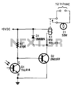
A phototransistor detects daylight. At dusk, it stops conducting, and Rl biases Q2, activating Kl, which turns on the light. At dawn, Ql begins to conduct, cutting off Q2. Kl deactivates, and the light turns off. The circuit utilizes a...
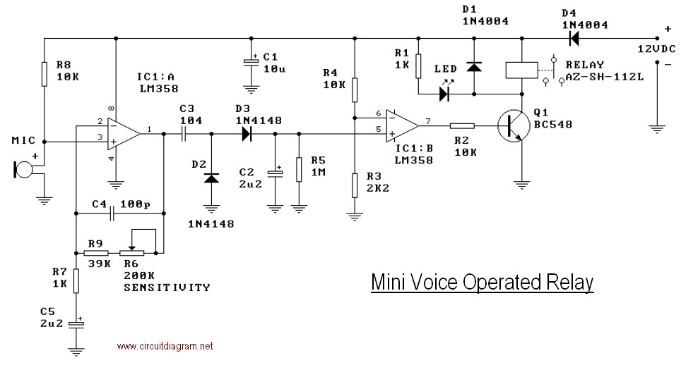
This mini-VOX voice-operated relay is based on a circuit published in Silicon Chip, September 1994, page 31. The off-delay time can be adjusted by varying resistors R3 and R4. Reducing R3 will result in a longer release time. It...