
dark detector led ldr
This dark detector LED circuit operates on the principle of light intensity variation. The LDR, which exhibits a decrease in resistance with increasing light levels, plays a crucial role in detecting ambient light conditions. In darkness, the resistance of the LDR increases significantly, allowing the circuit to function as intended. The transistor 2N2222 is configured in a common-emitter arrangement, where it acts as a switch that controls the LED based on the voltage across the LDR.
The 50K variable resistor provides flexibility in adjusting the sensitivity of the circuit. By varying this resistor, the threshold light level at which the circuit activates can be finely tuned, enabling the LED to respond to different lighting environments. The inclusion of a 1K resistor serves to limit the current flowing through the LDR, preventing potential damage from excessive current when the variable resistor is set to its minimum resistance.
The 330-ohm resistor connected in series with the LED ensures that the current flowing through the LED is within safe operating limits, thus prolonging the life of the LED while maintaining adequate brightness. The choice of four 1.5V batteries for power supply offers versatility in terms of battery size and type, making the circuit suitable for various applications, such as night lights or automatic lighting systems in dark environments. Overall, this simple yet effective circuit design demonstrates fundamental principles of electronic components and their interactions in response to environmental changes.Here is a project of a simple dark detector LED circuit. In the previous topic we have discussed a light activated LED circuit. By simply changing the positions of the resistors and LDR we have converted the circuit in a dark detector LED or dark activated LED circuit. The circuit will light up an LED when it will detect no light. An LDR (Photores istor) is used in this circuit for sensing the light and dark conditions, and transistor 2N2222 is working as a switch. When the LDR will detect no light it will open the transistor 2N2222 due to which the LED will light up.
The 50K variable resistor (VR) is used to adjust the desired light condition on which the LED will light up and 1K resistor is used to protect the LDR from direct connecting to the supply when the 50K variable resistor is on zero. The 330 ohms resistor is used to provide the required current to the LED. The circuit can be operated with four 1. 5V batteries of any size. 🔗 External reference
Related Circuits
The project involves installing LED strips in a car's tail lamps to replace conventional bulbs. The required lengths for the LED strips are 16 inches, 15 inches, and 14 inches to fit properly within the housings. The selected LED...
This circuit is a two-wire light level detector. The power supply and output signal are delivered through the same wires, utilizing a current loop. This two-wire light level detector circuit operates by using a single pair of wires for both...

Early in the exploration of high-power LEDs, such as the Luxeon 1 and 3-watt devices, the potential of Pulse Width Modulation (PWM) techniques for LED modulation was considered. This method theoretically minimizes distortion by making the LED's "Current versus...
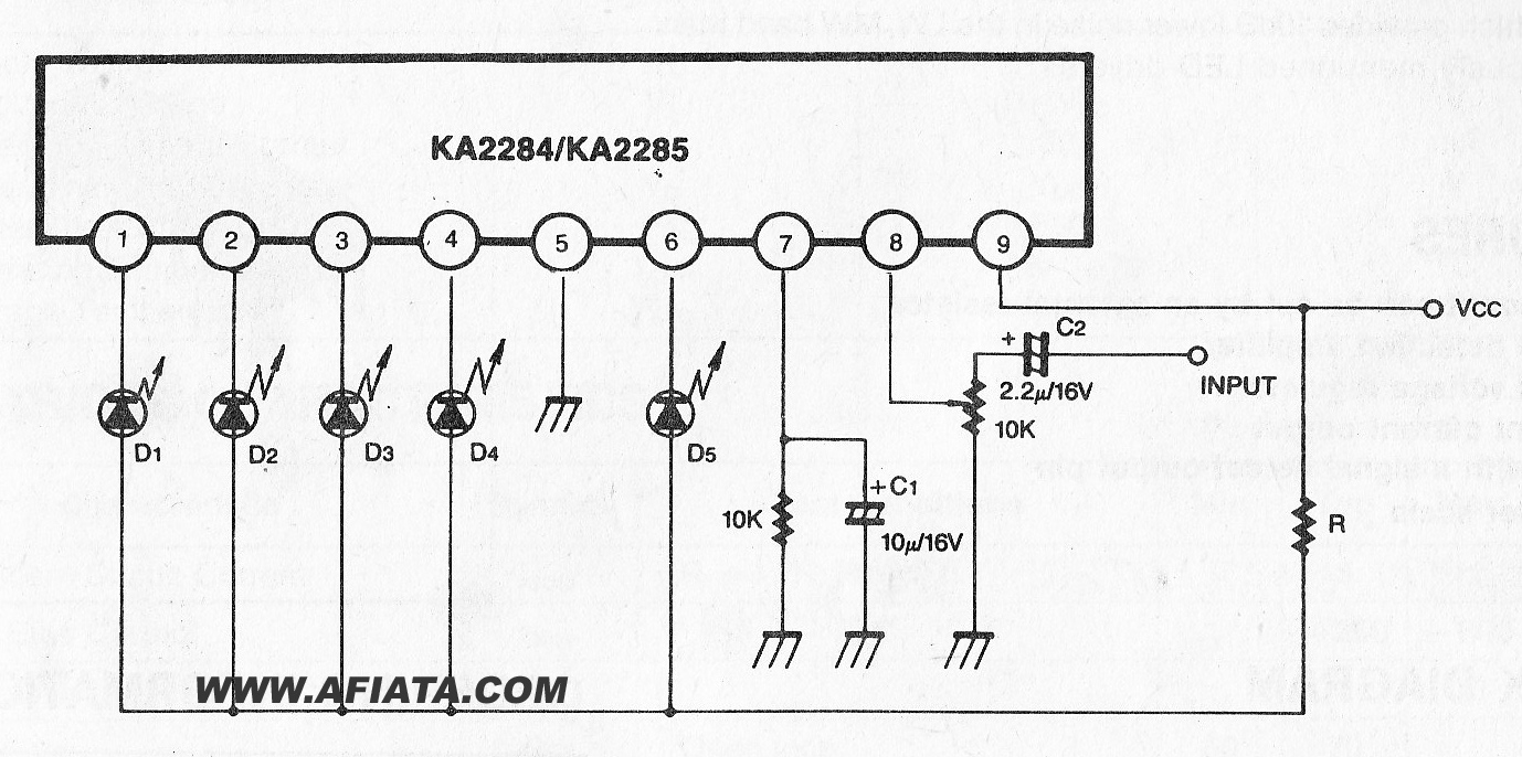
The KA2284 is a monolithic integrated circuit designed for 5-dot LED level meter drives with a built-in rectifying amplifier. It is suitable for both AC and DC level meters, such as VU meters or signal meters. The KA2284 integrated circuit...
A circuit designed to extract and measure the modulated carrier signal from an infrared (IR) remote control. This circuit does not physically separate control pulses from modulation; instead, it amplifies the complete received signal, allowing the waveform to be...
This circuit can detect whether a train is in a particular drive. The output is TTL and CMOS compatible and can be processed by such a computer. The simple circuit works. The driving voltage is connected to the two...