
DC Motor Controller using Transistor TIP31
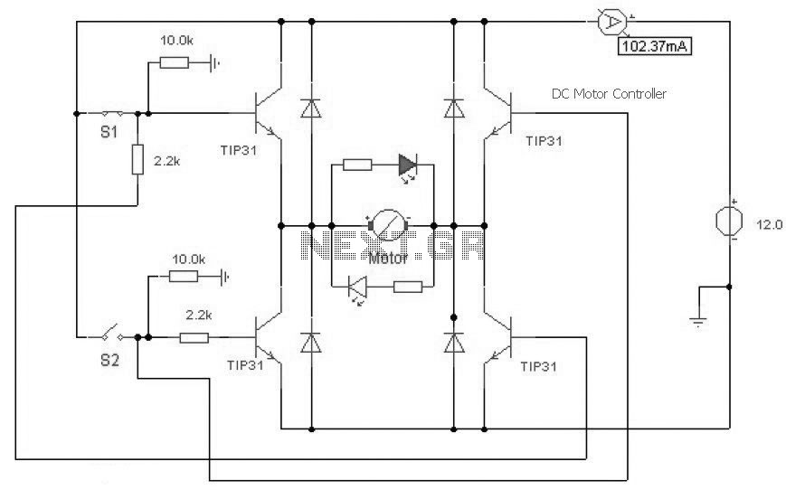
The described DC motor controller circuit utilizes an H-Bridge configuration to control the direction and speed of a DC motor. The TIP31 transistor, which is a power transistor, is employed in the circuit to handle the current required by the motor. The H-Bridge configuration allows for bidirectional control of the motor, enabling it to rotate in either direction based on the state of the control switches.
In this circuit, the switches S1 and S2 function as user inputs. When either switch is pressed, it closes the circuit and activates the corresponding leg of the H-Bridge, allowing current to flow through the motor in one direction or the other. If S1 is pressed, the motor will rotate in one direction, while pressing S2 will reverse the motor's rotation. The normally open configuration of these switches ensures that the motor remains off until the user actively engages one of the switches.
The inclusion of an LED indicator is a critical feature of this design. This LED visually signals the current direction of the motor's rotation. For instance, if the motor is set to rotate clockwise, the LED may light up in one color, while a counterclockwise rotation could trigger the LED to change to another color or turn off, depending on the specific design choices made in the circuit.
Overall, this DC motor controller circuit is a practical and efficient solution for applications requiring precise control of motor direction and operation, such as in robotics, automation systems, or remote-controlled devices. The simplicity of using a TIP31 transistor in conjunction with push-button switches makes this circuit accessible for both educational purposes and practical implementations.This is a DC motor controller circuit, built using transistor TIP31 based on H-Bridge concept. The switch S1 and S2 are normally open, push to close, press button switches. The LED function is to indicate the direction of motor rotation, y.. 🔗 External reference
Related Circuits

PIC development/testing board. This is a PCB design for a basic PIC16F877 development board. All that is required is a 4 MHz crystal, two 22 pF capacitors, and one 4.7 kΩ resistor. The PIC16F877 development board is designed to facilitate...
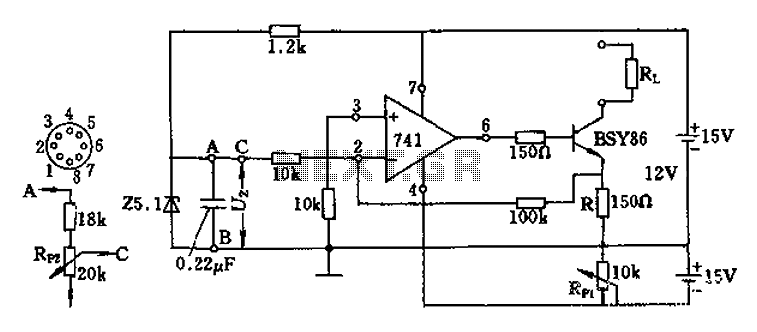
The Darlington transistor circuit BSY86 produces a large output current, with a maximum limit of 150 ohms. The output current is adjustable via resistor R and the RP1 potentiometer, maintaining constancy regardless of the load resistance Rl. The potentiometer...
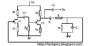
The Wien bridge oscillator utilizes a balanced Wien bridge as its feedback network. Two-stage common source amplifiers provide a 360-degree phase shift to the signal. The attenuation of the bridge is calculated to be 1/3 at the resonant frequency....
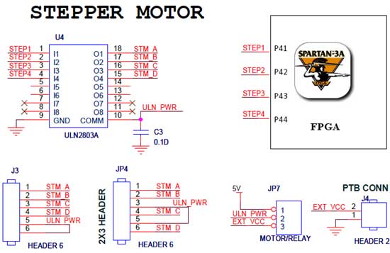
The Spartan-3an board features external interfacing for stepper motors, as illustrated in the accompanying figure. The stepper motor is driven by the ULN2803A, which is a high-voltage, high-current Darlington transistor array. The ULN2803 serves as a driver for the...
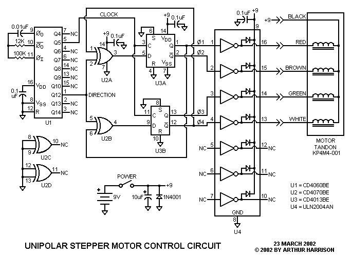
This circuit controls a small, four-phase, five-wire, unipolar stepper motor, commonly designated as the "KP4M4-001." This type of motor was utilized in many 5 1/4" floppy disk drives in older computers. Although now obsolete, such disk drives are often...
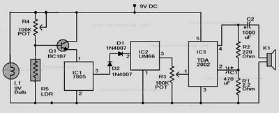
When there is no smoke, the light from the bulb directly illuminates the Light Dependent Resistor (LDR). In this condition, the resistance of the LDR is low, resulting in a voltage drop of less than 6V across it. Consequently,...