
DC Servo

The LTspice simulation of the Dxvideo preamplifier circuit featuring a DC servo offers valuable insights into the circuit's performance characteristics. The preamplifier is designed to amplify low-level audio signals while minimizing noise and distortion. The inclusion of a DC servo is crucial as it allows for the automatic adjustment of the DC offset in the output signal, ensuring that the output remains centered around zero volts, which is essential for preventing clipping and distortion in the subsequent stages of amplification.
In the simulation, the .four command is employed to analyze the circuit's frequency response and gain at specified frequencies, providing a clear understanding of how the preamplifier behaves across the audio spectrum. This command enables the extraction of key parameters such as gain, phase shift, and input/output impedance, which are critical for evaluating the overall performance of the circuit.
The schematic of the preamplifier typically includes operational amplifiers configured in a non-inverting configuration to achieve high input impedance and low output impedance. Additional components such as resistors and capacitors are strategically placed to set the gain and filter unwanted frequencies, while the DC servo circuit, often implemented with a feedback loop, continuously monitors and corrects the DC offset.
Overall, the LTspice simulation serves as a powerful tool for optimizing the design of the Dxvideo preamplifier with DC servo, allowing for adjustments and refinements before physical implementation. The insights gained from this simulation can lead to enhancements in audio fidelity and system stability.I done some more playing with the LTspice simulation of Dxvideo`s preamp-with-DC-Servo circuit. I have been using the .four command to have spice.. 🔗 External reference
Related Circuits
This is a simple servo tester which will comprehensively test the capabilities of almost any modern servo. It has two pushbuttons, CENTRE and SWEEP and a potentiometer which works as follows: - CENTRE Does exactly that, centers the servo,...
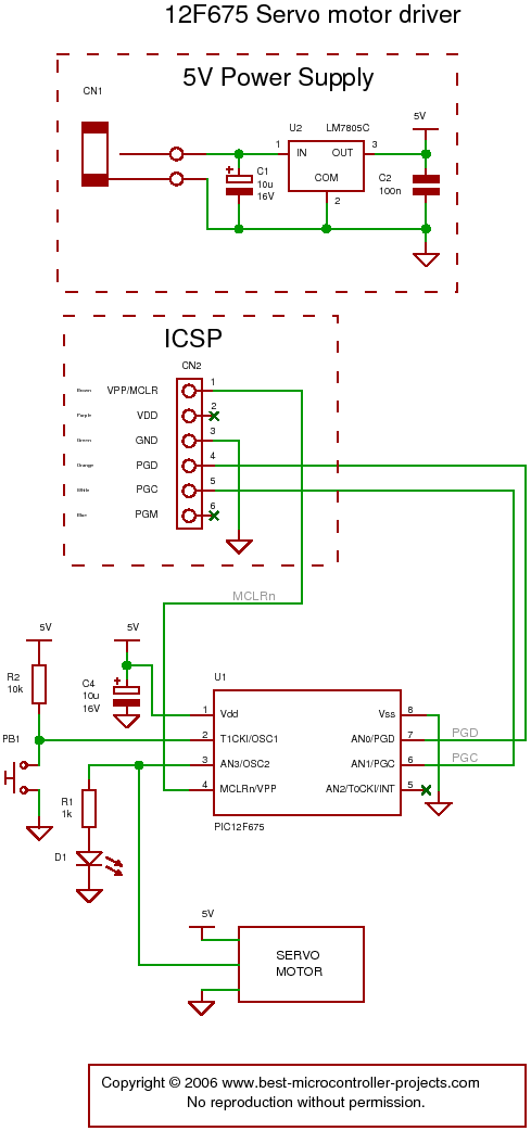
The following circuit illustrates a servo motor driver. This circuit is based on the 12F675 IC. Features include Timer 0 timing and a single control line. The servo motor driver circuit utilizing the 12F675 integrated circuit (IC) is designed to...
This simple DC servo motor circuit design can be utilized in various electronic projects. The circuit schematic illustrates that this DC servo motor driver employs a single integrated circuit along with a few external electronic components. For bidirectional DC...
This project describes a simple servo reverser that can be inexpensively constructed using a CD4001 NOR gate, four resistors, three capacitors, and one variable potentiometer (see schematic below). The proposed circuit utilizes the CD4001 NOR gate as the primary component...
In the circuit, when E and O are input DC voltages, the motor moves to a position corresponding to the voltage. A potentiometer, coaxially connected to the motor, is used for position feedback. When the given voltage equals the...

This servo system is designed to track the sun. Sunshine is focused onto a 50mm round image using an optical lens, and a 3DU33 photosensitive transistor is positioned at the light slit of AA' and BB'. It is essential...