
decibel meter circuit
The decibel meter circuit, or VU meter, is a valuable tool in audio systems for visualizing signal strength. This circuit typically utilizes an LM324 operational amplifier, which serves dual purposes: as a comparator to assess the input signal level and as an amplifier to enhance the signal for accurate representation. The circuit design allows for the integration of multiple LED indicators that light up in response to varying signal levels, providing a clear visual cue of audio intensity.
The input stage of the circuit is connected directly to the output of the audio amplifier, ensuring that the decibel meter accurately reflects the audio signal being sent to the speakers. The circuit is powered by a 12V DC supply, which is standard for many audio applications. The use of a variable resistor, VR500K, is critical for tuning the sensitivity of the meter. By adjusting this resistor, users can calibrate the circuit to respond appropriately to different signal levels, ensuring that the meter provides a meaningful representation of audio output without distortion or clipping.
Furthermore, the design can be adapted for various applications, such as in powered speakers or standalone audio amplifier systems. The simplicity of the circuit allows for easy assembly and integration into existing audio setups, making it an ideal project for both hobbyists and professional audio engineers. The visual feedback provided by the decibel meter enhances the user experience, allowing for real-time monitoring of audio levels and ensuring optimal performance of the audio system.The series of decibel meter function to determine the level of signal strength that is given to the speaker on the audio system. Decibel meter circuit is often also known as the VU meters on audio hifi system. For a series of decibel meters in this article displays strong technique with signal lights and LED. Decibel meter input circuit is taken f rom the output of the audio system that will connect to the speakers. The series uses a decibel meter this fruit as a comparator LM324 IC and 1 level amplifier with gain control. The series of decibel meter or VU meter is quite simple to make and circuit details can be seen in the following figure.
The series of decibel meters above requires 12VDC voltage source and an input signal from the audio power output that is connected to the speakers. The series of decibel meters can be installed on powered speakers or other audio amplifier system. To adjust the audio signal reception sensitivity is set by adjusting the value VR500K which serves as feedback and reinforcement factors will affect the amplifier circuit ahead of the decibel meter.
🔗 External reference
Related Circuits

This circuit produces a soft turn-on for halogen lamp filaments upon powering up. The MOSFET used is a BUZ10, which has a resistance of 0.2 ohms. Resistors R1, R2, and capacitor C1 set the turn-on rate, while diode D1...
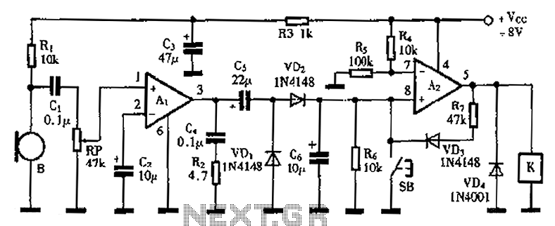
A practical voice-activated switch is presented. An A1 amplifier is connected to a conventional microphone (B) that picks up the audio control signal, which is then amplified. After amplification, the signal passes through components C5, VD1, and VD2, forming...
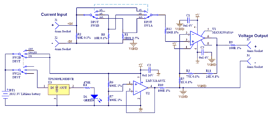
The µCurrent is in many cases also able to improve upon your meters current range accuracy by using your meters more accurate mVDC or mVAC voltage ranges instead to display the DC or AC current. With AC the frequency...
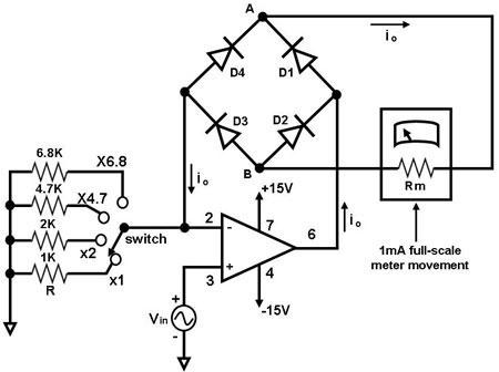
The primary component of this circuit is an operational amplifier (such as the 741 or 351), configured as an amplifier with a feedback circuit that consists of a diode bridge full-wave rectifier. An ammeter is connected to the rectifier...
All car batteries require a 12V battery charger, which also applies to marine, RV, and power sports batteries. The high-efficiency lead-acid batteries available today necessitate more effective charging techniques. The battery charger is a crucial tool for prolonging battery...
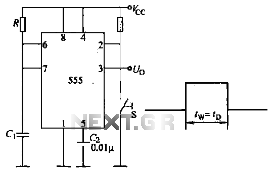
Introduction to the circuit schematic depicted in Figure 3-3. In this configuration, the 555 timer is utilized in a monostable mode, typically activated by a normally open push button switch. The circuit operates in an S-shaped state, where the...