
Delaying the release of DC relay circuit
The circuit design outlined involves the use of capacitive components to manage the timing characteristics of relay operations. The relay serves as an electromechanical switch that can be activated by an electrical signal, with the timing of this activation and subsequent deactivation being critical in control applications. The capacitor in the circuit charges through the relay coil, and this charging process influences the timing of the relay's activation.
When the relay is energized, the capacitor begins to charge, and the time taken for the voltage across the capacitor to reach a specific threshold determines how quickly the relay pulls in. Conversely, when the relay is de-energized, the capacitor discharges through the relay coil, introducing a delay before the relay releases. This delay is essential in applications where immediate deactivation could lead to undesirable outcomes, such as mechanical shock or electrical transients.
The equation provided for estimating the maximum time delay incorporates both the resistance of the circuit and the capacitance of the capacitor. It is important to note that the total resistance (R) includes both the circuit resistance (R) and the resistance of the relay coil (RL), which together influence the charging and discharging rates of the capacitor. The capacitance (C) is a critical parameter, as it directly affects the time constant of the circuit, which is defined as τ = R × C.
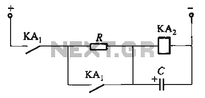
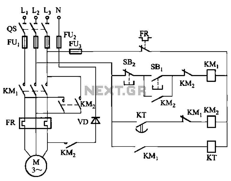
In practical applications, selecting the appropriate values for R and C allows for fine-tuning of the delay characteristics to meet specific operational requirements. This flexibility is beneficial in various control systems, ranging from industrial automation to consumer electronics, where precise timing is crucial for reliable performance.In order to meet the needs of the control loop, often require electromagnetic relay or transistor relay to accelerate or delay action, from action to constitute accelerate or delay circuit. Circuit shown in Figure 6-23. These types of circuit is the use of a capacitor charging and discharging of the relay coil to delay the release time Ran. Figure 6-23 (a) ~ (c) is the instantaneous pull, delayed release circuit; Figure 6-23 (d) to pull delay, release delay circuit.
The maximum time delay relay may be estimated by the following equation: t = 0 85R.. CX10-6 (s) where R: - the total circuit resistance, R: = R + RL, 0; R resistance, 0; foot L- relay coil resistance, N; C capacitance, pF.
Related Circuits
Here is the schematic diagram for a 20 Watt driver. I developed this circuit in 1985, and used it to build a lamp that found much use both as camping light and as emergency light during the then-frequent power...
This UHF wideband amplifier (Ultra High Frequency amplifier) provides a total gain of 10 to 15 dB in the frequency range of 400 to 850 MHz, making it suitable for areas with weak TV signals. For optimal performance, the...
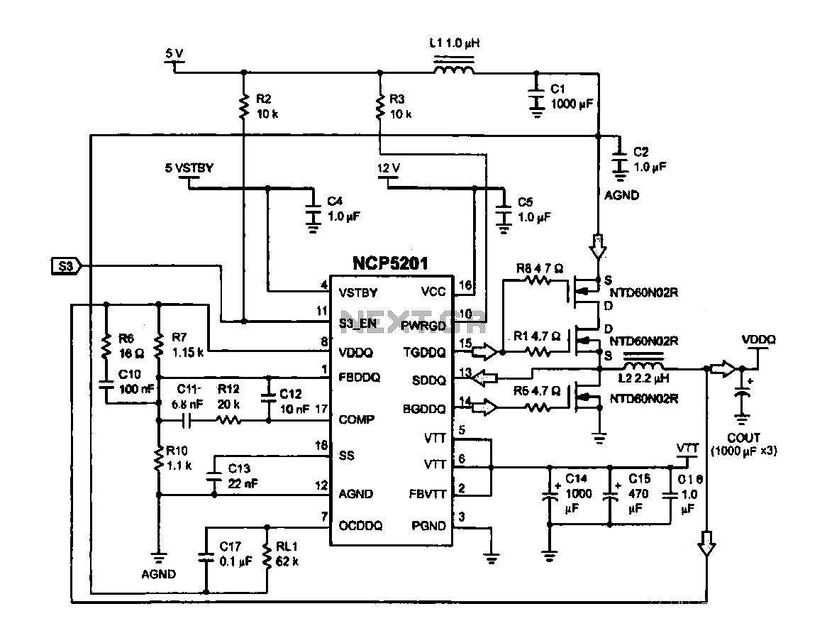
Computer memory power supply circuit (NCP5201). This circuit illustrates a typical power supply configuration for computer memory, utilizing the NCP5201 power management chip. It features a dual-output design. The NCP5201 is a highly integrated power management solution designed specifically for...
The circuit features a serial coded modulated control signal that amplifies and transmits high-voltage isolation. It utilizes a 556 timer-based circuit along with resistors R1, R2, capacitors C1, and R3, R4, C2 to form two astable multivibrators. The circuit...
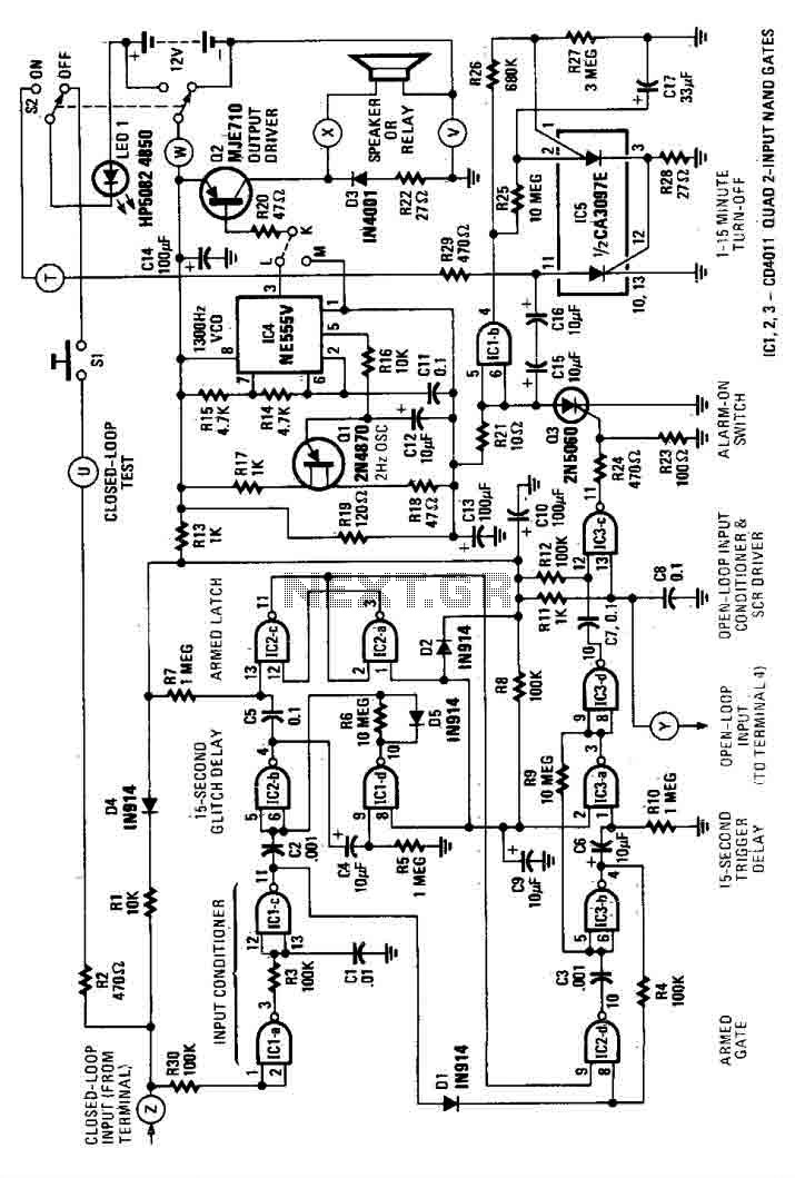
This house alarm circuit features both open and closed loop sensors and includes a self-shutdown function. The delay after triggering can be adjusted between 1 minute and 12 minutes, while the delay before triggering is set at 13 seconds....
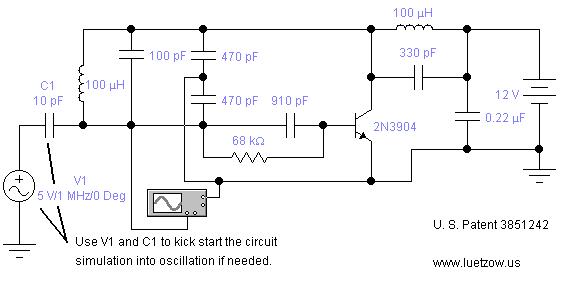
The oscillator circuits presented on this page are derived from expired or non-maintained U.S. Patents. All circuits are formatted for "Electronic Workbench 5.12" or "Multisim 7" circuit simulation software. A note regarding SPICE simulation of electronic oscillator circuits: all...
Warning: include(partials/cookie-banner.php): Failed to open stream: Permission denied in /var/www/html/nextgr/view-circuit.php on line 713
Warning: include(): Failed opening 'partials/cookie-banner.php' for inclusion (include_path='.:/usr/share/php') in /var/www/html/nextgr/view-circuit.php on line 713