
Beeping Down Counter Circuit

The schematic represents a well-structured electronic circuit that incorporates various components to achieve its functionality. Starting from the left, the state machine utilizes four NOR gates, enabling a three-state operation that facilitates transitions between set and start conditions based on user input. The countdown mechanism is initiated when the countdown value reaches zero, prompting the system to enter the 'trigger' state, which is crucial for the operation of the timer.
The use of decade counters is a strategic choice, as these components are configured to load a preset value of 25 when the set state is engaged. The outputs from the decade counters are then fed directly into the 4511 LED drivers, which are responsible for converting the binary output from the counters into a format suitable for driving the common-cathode 7-segment displays.
The integration of the 556 timer, which contains two independent 555 timer circuits, enhances the functionality of the schematic. One timer serves as the primary clock, emitting a frequency around 1 Hz, which is essential for timing applications. The second timer, configured to generate a sound frequency between 2-5 kHz, adds an auditory signal to the system, providing feedback to the user during operation.
It is important to note that the circuit is specifically designed for common-cathode 7-segment displays. This design choice necessitates careful consideration of the connection and configuration of the display components to ensure proper functionality. While the schematic indicates a single resistor connected between the common cathode pin and ground, it is advisable to incorporate individual resistors for each of the A-G inputs to limit current and protect the display from potential damage. This adjustment would enhance the reliability and longevity of the circuit in practical applications.The schematic for this project isn`t too, too bad to look at even though it`s not the best drawing/layout for a schematic that I`ve ever done. The basic flow is from left to right. Left side is the state machine, then the 555 timers, then counter circuitry and finally the 7 segment LED output circuitry.
The theory section explained this already a little bit, but the 4 NOR gates will act like a 3 state machine, with the buttons triggering between set and start states and the count down value of 00 moving the system to the `trigger` state. The decade counters are hardwired to load the value of `25` into the system when the set state is activated.
The outputs from these counters go directly into the 4511 LED drivers to set the count value on the display. The 556 IC appears as two 555 timers in the circuit. As discussed before one is used as a master or system clock at about 1 Hz and the other is used for generating the 2-5 KHz beep sound.
This system is made for common-cathode 7 segment displays, so be sure that`s what you`ve got. Similarly, it would be wiser to add resisters before the A-G inputs, but I got lazy and added a single resistor between the common cathode pin and ground. 🔗 External reference
Related Circuits
This amplifier circuit is designed to enhance TV signals in the UHF range. It employs a low-noise transistor, providing an amplification of 10 to 15 dB within the frequency spectrum of 400 MHz to 850 MHz. It is crucial...
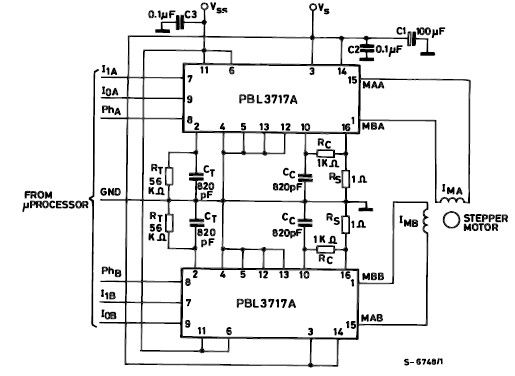
The PBL3717A stepper motor driver is a monolithic integrated circuit that controls and drives one phase of a bipolar stepper motor utilizing chopper control for phase current regulation. Current levels can be selected in three increments using two logic...
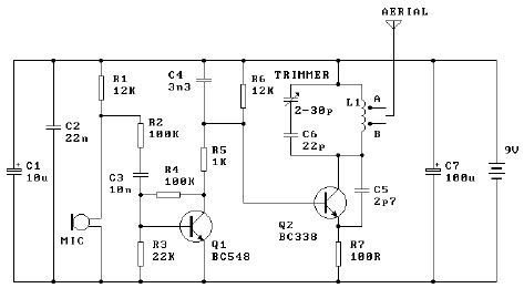
The tuned coil L1 has two output tap points for the antenna connection, labeled "A" and "B." Both outputs are low-level, allowing the user to select between a stable low range or a more unstable but higher range. Tap...
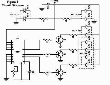
It consists of a 4047 low-power monostable/astable multivibrator, IC1, used in the astable mode to provide the timing pulses to control the flash rate of the LEDs. To accomplish the astable mode, pins 4, 5, 6, and 14 are...
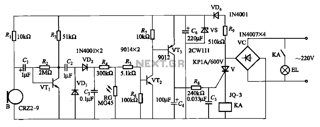
A resistor R8, capacitors Cd, and a thyristor V AC switch form a delay circuit. The lamp's lighting delay time is determined by the resistor Rs and capacitor C4, with a delay of approximately 40 seconds as indicated in...
This intelligent electronic lock circuit is constructed using only transistors. To unlock this electronic lock, the user must press tactile switches S1 through S4 in sequence. For added security, these switches can be labeled with different numbers on the...