
Digital Main Voltage Indicator
The solid-state voltmeter circuit is designed to provide a reliable and accurate representation of mains voltage, making it suitable for applications that require continuous monitoring. The use of solid-state components eliminates the mechanical issues associated with analog voltmeters, such as wear and sensitivity to vibrations. The LED bar graph serves as a visual indication of the voltage level, allowing for quick assessment.
The circuit architecture is centered around a 16-channel multiplexer (CD4067B) and a binary counter (CD4029B), which work in tandem to select the appropriate voltage level for display. The NE555 timer configured as an astable multivibrator generates the clock signal required for the counter, ensuring that the multiplexing of the presets occurs in a timely manner. The output from the presets, which correspond to the set voltage levels, is routed through the multiplexer, allowing only the selected voltage to be passed to the comparator.
The comparator (LM358) plays a crucial role in determining when the sensed voltage exceeds the reference voltage. This functionality allows the circuit to accurately indicate voltage levels, ensuring that the LED bar graph reflects the true state of the mains voltage. The design incorporates a buffer to stabilize the reference voltage, enhancing the reliability of the voltage detection process.
For calibration, the use of an auto-transformer allows for precise setting of each preset, ensuring that the circuit can accurately represent varying input voltages. The recommendation to implement additional power supply components is crucial for maintaining circuit performance across a wide voltage range, thereby enhancing the robustness of the design.
Overall, this solid-state voltmeter circuit provides an efficient and effective solution for monitoring mains voltage, combining modern electronic components with practical design considerations to ensure accurate and reliable operation in various applications.Continuous monitoring of the mains voltage is required in many applications such as manual voltage stabilisers and motor pumps. An analogue voltmeter, though cheap, has many disadvantages as it has moving parts and is sensitive to vibrations.
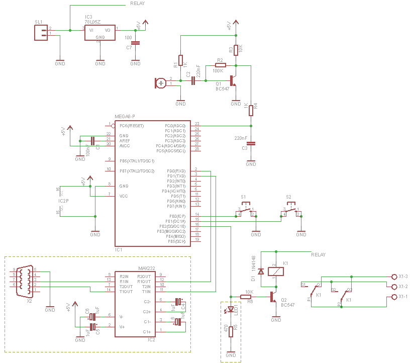
The solidstate voltmeter circuit described here indicates the mains voltage with a resolution that is comp arable to that of a general-purpose analogue voltmeter. The status of the mains voltage is available in the form of an LED bar graph. Presets VR1 through VR16 are used to set the DC voltages corresponding to the 16 voltage levels over the 50-250V range as marked on LED1 through LED16, respectively, in the figure. The LED bar graph is multiplexed from the bottom to the top with the help of ICs CD4067B (16-channel multiplexer) and CD4029B (counter).
The counter clocked by NE555 timer-based astable multivibrator generates 4-bit binary address for multiplexer-demultiplexer pair of CD4067B and CD4514B. The voltage from the wipers of presets are multiplexed by CD4067B and the output from pin 1 of CD4067B is fed to the non-inverting input of comparator A2 (half of op-amp LM358) after being buffered by A1 (the other half of IC2).
The unregulated voltage sensed from rectifier output is fed to the inverting input of comparator A2. The output of comparator A2 is low until the sensed voltage is greater than the reference input applied at the non-inverting pins of comparator A2 via buffer A1. When the sensed voltage goes below the reference voltage, the output of comparator A2 goes high. The high output from comparator A2 inhibits the decoder (CD4514) that is used to decode the output of IC4029 and drive the LEDs.
This ensures that the LEDs of the bar graph are on` up to the sensed voltage-level proportional to the mains voltage. The initial adjustment of each of the presets can be done by feeding a known AC voltage through an auto-transformer and then adjusting the corresponding preset to ensure that only those LEDs that are up to the applied voltage glow.
It is advisable to use additional transformer, rectifier, filter, and regulator arrangements for obtaining a regulated supply for the functioning of the circuit so that performance of the circuit is not affected even when the mains voltage falls as low as 50V or goes as high as 280V. During Lab testing regulated 12-volt supply for circuit operation was used. ) 🔗 External reference
Related Circuits

This circuit is a precision amplifier with digital control, designed for signal conditioning of low-output transducers operating in the millivolt range. The resistors R3 to R6 can be user-selected, with values ranging from 1 kilo-ohm to 1 mega-ohm, allowing...
The DD-2 is a highly regarded digital delay pedal that emulates an analog sound. It was initially sold from 1983 until it was discontinued in 1986, after which it was relaunched without any modifications as the DD-3 (noting that...
This project outlines the construction of a digital voltmeter utilizing a PIC microcontroller. A character LCD based on the HD44780 is employed to display the measured voltage. The PIC microcontroller used is the PIC16F688, which features 12 I/O pins,...
The pulser is designed to switch the mains voltage on and off at intervals ranging from just under one second to up to 10 minutes. This functionality is particularly useful for testing mains-operated equipment over extended periods or for...

The following circuit illustrates a UHF Indicator Wavemeter Circuit Diagram. This circuit utilizes dual BF494 transistors. Features: the oscillator is... The UHF Indicator Wavemeter Circuit is designed to measure and indicate the frequency of ultra-high frequency (UHF) signals. The circuit...
The chip tester verifies the functionality and timing of a variety of 7400 series integrated circuits. Students taking Digital Logic Design Lab use these chips often in their laboratory. The IC to be tested should be placed on the...
Warning: include(partials/cookie-banner.php): Failed to open stream: Permission denied in /var/www/html/nextgr/view-circuit.php on line 713
Warning: include(): Failed opening 'partials/cookie-banner.php' for inclusion (include_path='.:/usr/share/php') in /var/www/html/nextgr/view-circuit.php on line 713