
Ding-Dong sound generator
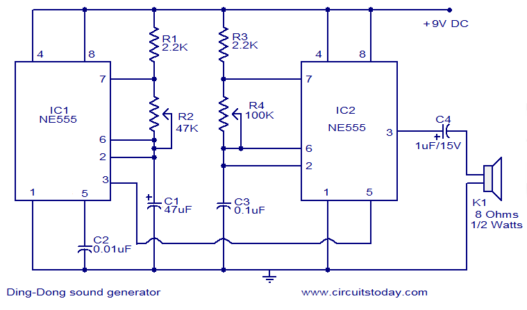
The circuit employs two NE555 timer ICs to generate a sound that alternates between two distinct tones, resembling a doorbell chime. In the astable mode, the first NE555 timer (IC1) continuously switches between high and low states, generating a square wave output at a frequency of 1 Hz. This output serves as a clock signal that controls the operation of the second NE555 timer (IC2).
IC2 is configured in a monostable mode, where it produces a pulse of variable width depending on the control voltage applied to its control pin (pin 5). By connecting the output of IC1 to this control pin, the pulse width—and thus the frequency—of IC2 can be adjusted dynamically. The frequency modulation creates a variation in the tone of the sound produced, allowing for a pleasing and recognizable ding-dong chime.
The circuit's design incorporates adjustable resistors and capacitors for tuning the frequencies of both timers, enabling customization of the sound characteristics. The output from IC2 can be connected to a small speaker or piezo buzzer to produce the audible sound. The overall functionality of the circuit is simple yet effective, making it suitable for various applications, including doorbells and novelty sound effects.This is the circuit diagram of a ding dong sound generator based on two NE555 timer ICs. The circuit is designed to toggle between two adjustable frequencies to produce the ding dong sound. The first NE555 (IC1) is wires as an astable multivibrator operating at 1Hz. The frequency of the second NE555 (IC2) is modulated by the output from the first I C. This is attained by connecting the output of first IC to the control pin (pin5) of the second IC. The tone of the sound depends on the frequency of the second IC and the changeover time depends on the frequency of the first IC. 🔗 External reference
Related Circuits
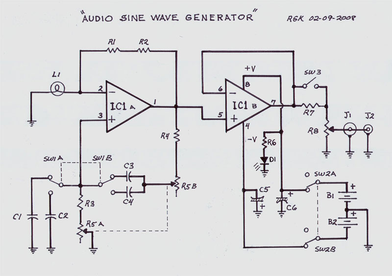
This single integrated circuit (IC) design is based on the Wien Bridge Oscillator, generating low distortion sine waves within a frequency range of 15 Hz to 22 kHz across two output voltage levels: approximately 0-250 mV and 0-2.5 Vrms....
A Georgia Republic inventor, Tariel Kapanadze, claims to have invented a 5 kilowatt free energy generator. In a demonstration video, the device appears to produce copious amounts of energy from no visible source. More: The components apparently include a...
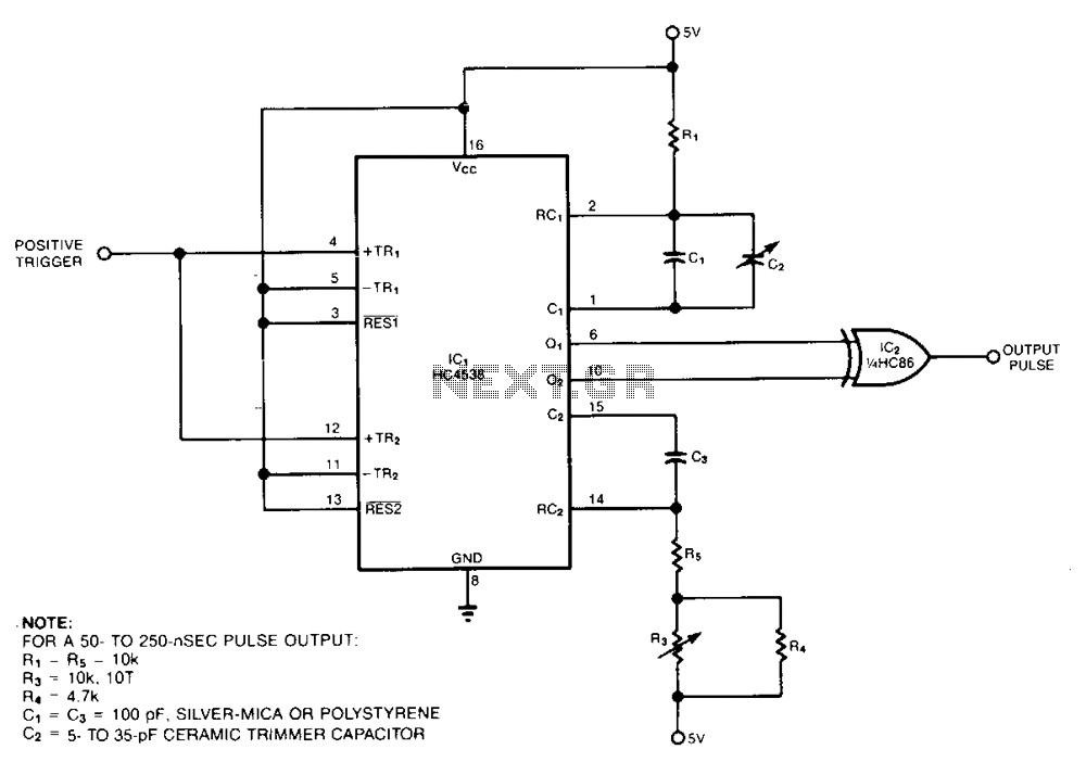
The pulse generator consists of two low-power CMOS chips that produce a precise pulse width ranging from 50 to 500 ns. IC1 is a dual monostable multivibrator (one shot) where each positive trigger pulse initiates simultaneous positive output pulses...
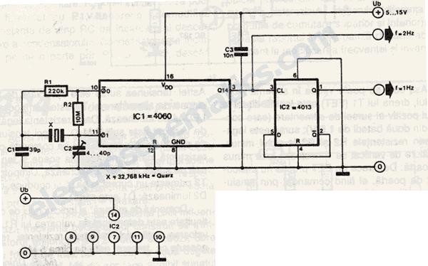
This 1 Hz and 2 Hz generator or oscillator is constructed using a 4060 IC as the oscillator and a 14-bit counter. To achieve a 1 Hz signal from the 4060, a 1/2 4013 flip-flop is utilized. This circuit...
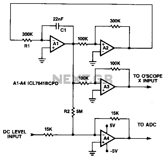
This circuit generates a symmetrical 10 mV peak-to-peak triangle waveform that is summed with a DC level and connected to the analog input for noise and DNL testing. The DC level input offsets the triangle waveform over the input...

A function generator virtual oscilloscope designed using a sound card serves as a multi-functional device, incorporating a microcontroller-based function generator. This project represents the implementation of a graduation thesis. A function generator typically generates various voltage waveforms, such as...