
Digital Clock with Timer and Solar Panel Regulator circuit

This combination device integrates multiple functionalities, including timekeeping, load control, and battery management, into a coherent system. The timer function is crucial for applications where energy management is essential, ensuring that the load operates only during designated intervals, thus optimizing battery usage. The use of a 4040 binary counter allows for flexible timing configurations, enhancing versatility in various applications. The clock circuit's reliance on a 32,768 Hz crystal oscillator ensures high accuracy in timekeeping, which is essential for both the timer and the display.
The display circuit, leveraging seven-segment LED technology, provides clear visual feedback of the time, while the multiplexing system allows for efficient use of display resources, minimizing the number of active components at any given time. The dual-functionality of the DPDT switch simplifies user interaction, allowing for intuitive adjustments to time settings without needing separate controls.
The voltage regulation system is pivotal for ensuring the longevity and reliability of the deep cycle battery, which is essential in solar applications where energy availability can fluctuate. The integration of a charge indicator and a battery condition indicator provides users with immediate feedback on battery health, allowing for proactive maintenance and minimizing the risk of system failure.
Overall, the design reflects a thoughtful integration of components that work synergistically to provide a reliable and efficient solution for solar energy management and timekeeping.This is a combination digital clock timer and solar panel charge controller used to maintain a deep cycle battery from a solar panel. The timer output is used to control a 12 volt load for a 32 minute time interval each day. Start time is set using 9 dip switches and ends 32 minutes later. The 32 minute duration is set by selecting the 5th bit 5 = 32) of a 4040 binary counter (pin 2). The timer also has a manual toggle switch so the load can be manually switched on or off and automatically shuts off after 32 minutes. The time duration can be longer or shorter (8, 16, 32, 64, 128, 256 minutes etc. ) by selecting the appropriate bit of the counter. The timer circuit is shown in the lower schematic just above the regulator. The basic clock circuit (top schematic below) is similar to the binary clock (on another page) and uses 7 ICs to produce the 20 digital bits for 12 hour time, plus AM and PM.
A standard watch crystal oscillator (32, 768) is used as the time base and is divided down to 1/2 half second by the 4020 binary counter. One half of a 4013 data latch is used to divide the 1/2 second signal by 2 and produce a one second pulse that drives the seconds counter (74HC390 colored purple).
The minutes are advanced by decoding 60 seconds (40 + 20) and then resetting the seconds counter to 0 and at the same time advancing the minutes counter. The same procedure is used to advance the hours. The second half of the 4013 latch is used to indicate AM or PM and is toggled by decoding 13 hours and resetting the hours to 0 and then advancing the hours to "one".
The clock display circuit is shown in the second drawing below and uses 6 more ICs to decode the binary data and drive four seven segment LED displays. The 10s of hours digit is driven with a single 3904 transistor. Two multiplexer circuits (4053) are used to manually select either minutes or seconds for the right two display digits.
The two switches shown between the 4053s and below the left 4053 are both part of one DPDT switch which selects either seconds or minutes for the 1X and 10X digits. This switch is shown in the seconds position and the hours digits are blanked with a low signal on pin 4 of the 4511.
The display can also be toggled on and off (totally blank) using a set/reset latch made from a couple 74HC00 NAND gates. A momentary DPDT switch is used to control the latch and toggle the display on or off. The second pole of this switch is used on the upper drawing (connected to the run/stop switch) to set the hours and minutes.
Thus this same switch performs both functions of blanking the display and setting the time. The run/stop switch is shown in the normal running mode and supplies a low signal to a NAND gate which prevents accidental setting the time while the clock is running. The run/stop switch also turns on the display (through the diode D2) when in the stop position. The procedure for setting the clock would be to set the (run/stop) switch the stop position and the (seconds/minutes) switch to the minutes position.
Then toggle the momentary switch to set minutes and hours of the current time plus one minute. The clock can then be started with the run/stop switch at precisely the right time (+/- 0. 5 seconds). The voltage regulator in the lower drawing maintains the battery at 13. 6 volts and also supplies the clock and timer circuits with 4. 3 volts. The charge LED indicator only comes on when the regulator is supplying max charge to the battery. When the battery voltage reaches 13. 6 the regulator reduces the current to whatever is necessary to maintain the voltage and the charge indicator will turn off. The unit I built also included a battery condition indicator (voltmeter using 4 LEDs) to indicate the battery condition so that a failure of the regulator would be indicated by the charge indicator LED turned off and less than 4 LEDs lit on the voltmeter.
🔗 External reference
Related Circuits
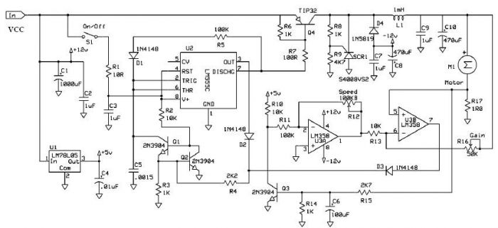
Speed regulation is achieved by monitoring the motor current with resistor R17 and utilizing it as positive feedback to offset motor resistance losses. The gain potentiometer should be adjusted to just below the threshold where motor speed begins to...
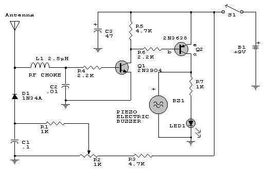
This electronic RF detector project is constructed using common transistors and a few standard electronic components. The RF detector is capable of responding to RF signals below the standard broadcast band and extending to over 500 MHz, providing both...
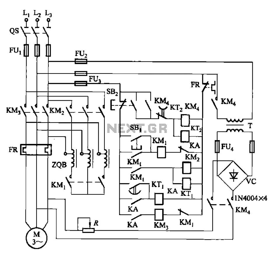
The circuit is illustrated in Figure 3-141. It includes a line autotransformer for voltage starting and dynamic braking. The circuit features a buck start button (SBi) and a stop button (SBz). The buck start-up time is controlled by the...
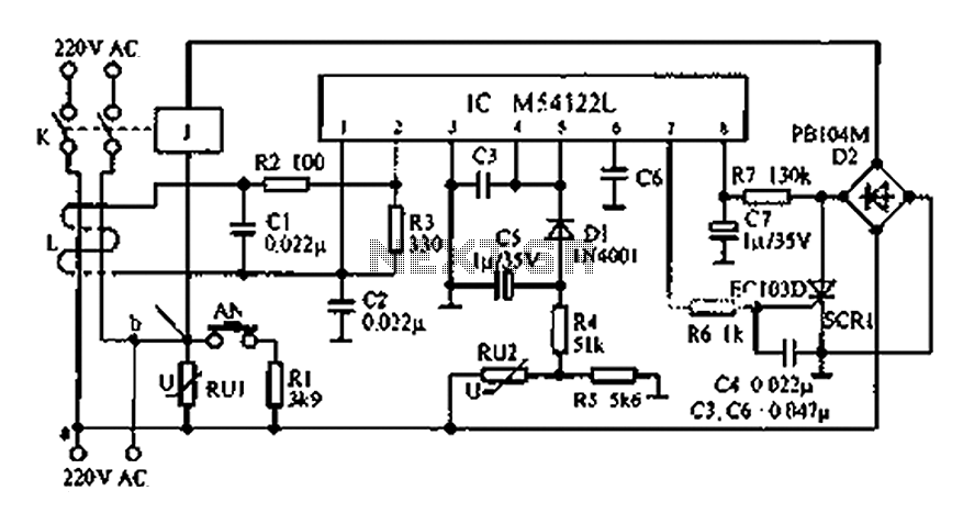
The multifunction leakage protection switch utilizes the Nissan ASIC M54122L. It is designed to serve as a multi-function leakage protection switch. In the event of leakage or electric shock, the magnetic field generated through the inductor line and neutral...
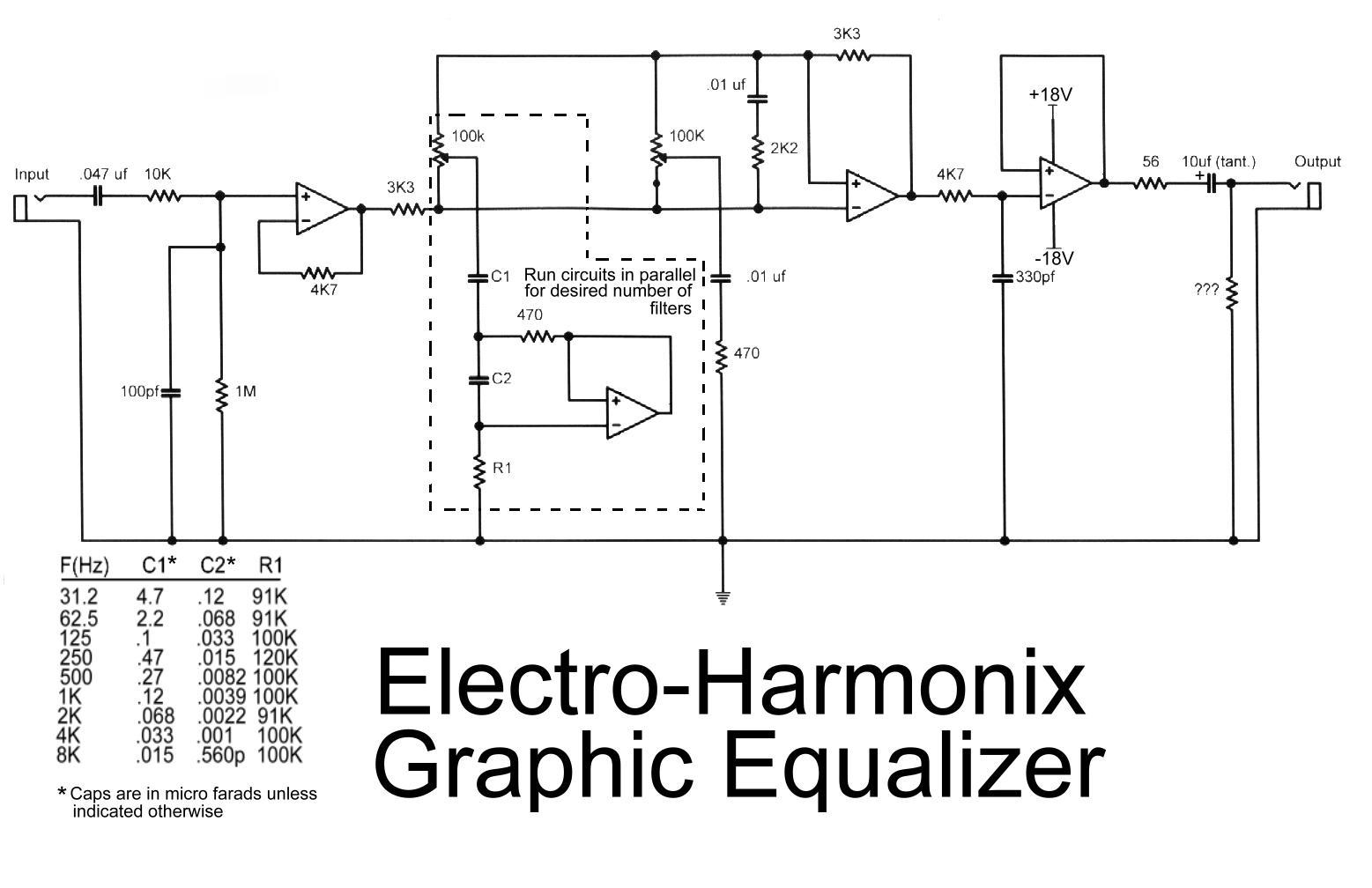
This is the diagram of the Electro-Harmonix graphic equalizer. The number of channels can be specified according to requirements by paralleling the components: C1, C2, R1, an operational amplifier, potentiometer, and a 470-ohm resistor. The frequency to be boosted...
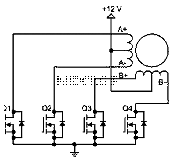
A bipolar stepper motor drive circuit is presented, utilizing eight transistors to operate two phases. This bipolar drive circuit can accommodate both four-wire and six-wire stepper motors; however, it is primarily designed for four-wire bipolar configurations, which can significantly...