
Direction Sensitive Light Barrier
The circuit operates based on the principles of infrared light transmission and reception. The IR transmitter emits modulated light that is detected by the receivers. When a person crosses the light barriers, the interruption of the IR beam results in a change of state in the output signals of the integrated circuits. The use of two receivers allows for detection of the direction of movement, which is essential for the intended application of controlling lights in a restroom.
For the installation, the IR transmitters should be positioned at an optimal height and angle to ensure reliable operation. The TSOP1736 receivers should be shielded from direct sunlight to prevent false triggering, although the circuit is designed to mitigate such interference. The relay used to control the light should be rated for the load it will be switching, ensuring safe and reliable operation. The design of the circuit can be adjusted based on the specific requirements of the installation environment, such as the distance between the barriers and the type of lighting being controlled.
Overall, this light barrier circuit effectively integrates sensing and control technology to automate lighting, enhancing convenience and energy efficiency in spaces such as restrooms. The modularity of the circuit allows for customization and adaptation to various applications beyond lighting control.With two light barriers closely positioned one after the other it is possible to establish in which direction they have been crossed. If, for example, you place it at the entrance of the toilet then you can use it to control the lights: on when entering and off when leaving the room.
The circuit for this has many similarities with the modulated light barrier appearing else-where in this Summer Circuits issue. There are two ways to position the light barriers, namely a completely duplicated installation in opposing directions (this to prevent mutual interference) and a version with one IR transmitter and two receivers. Both types of installation are shown here, which one is most suitable depends on the actual application.
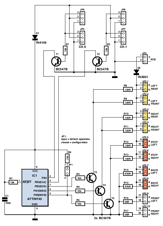
When used in a doorway, one transmitter is sufficient if the receivers are placed about 5 cm apart. With a wider passage, an installation with two separate IR-transmitters is a better solution. This circuit has a range of several meters, even if the sun shines directly on the receiver! We use the exact same IR-transmitter(s) as for the modulated light barrier. For the installation with two separate IR-transmitters it is sufficient to duplicate R6, T1, D1, C3 and R7 from the circuit of the modulated light barrier. Output OUT (pin 3) of IC2 can drive two of these IR-drivers without any difficulty. The receivers are slightly different than those of the modulated light barrier and the circuit is the same for both types of installation.
We again use the TSOP1736, which is sensitive to IR-light that is modulated at a frequency of 36 kHz. D2, R8 and C4 ensure that the received pulses from IC3 at the output of IC5a result in a 1` when the beam is not interrupted.
When the beam is interrupted this output will become a 0` within about 1 ms. In the same way IC5b generates a 0` when IC4 stops receiving IR-light. The 4013 CMOS-IC used here contains two D-flipflops, of which we use only one. The instant that light barrier 2 (IC4) is unblocked again, is used to clock the state of light barrier 1 (IC3) through to output Q1. This signal drives the relay via T2, which operates the light in the room. The circuit therefore turns the light on or off the moment that light barrier 1 is uninterrupted. 🔗 External reference
Related Circuits
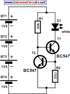
The author gifted a radio-controlled (RC) model car to his partner. She enjoyed it but suggested that adding realistic lights would enhance the experience. Consequently, the author returned to his workshop, utilized his soldering iron, and began outfitting the...

This circuit utilizes low-voltage AC to power a string of approximately 50 bi-color LEDs, with two LEDs connected in inverse parallel. The power supplied to the LEDs is managed by a Triac and two optocouplers, whose phototransistors are also...

This 6V battery-operated doorbell light circuit can be connected in parallel with any existing AC 230V doorbell. When the doorbell switch is pressed, the bell sounds as usual, and the AC mains supply available across the doorbell is routed...
Physicians and repair engineers frequently utilize small light pens for visual examination purposes. Although these pens are rugged and can be expensive, their vulnerability lies in the bulb, which is a replaceable component. In practice, this often translates to...

This circuit is capable of generating up to 1 W of audio power to drive a speaker or horn. When the CDS cell is exposed to light, its resistance decreases, activating NOR gate (a). This activation causes gates (a)...
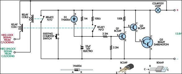
This circuit functions as a courtesy light extender for automobiles, providing illumination for a duration of 15 to 20 seconds. It is triggered by the conventional method of opening a car door, while also sampling the... This circuit is designed...